Arduino UNO Motion-Activated Servo and LED Control System
Circuit Documentation
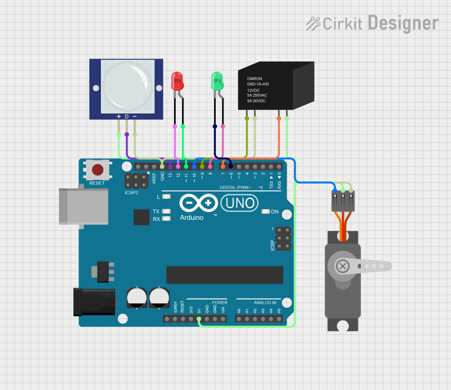
Summary
This circuit is designed to detect motion using a PIR motion sensor and respond by turning on a red LED, activating a relay, and rotating a servo motor. When motion is detected, the red LED turns on for 10 seconds. After this period, the relay is activated, and the servo motor rotates 90 degrees for 3 seconds before returning to its original position.
Component List
PIR Motion Sensor (Wokwi Compatible)
- Pins: VCC, OUT, GND
- Description: Detects motion and outputs a high signal when motion is detected.
LED: Two Pin (red)
- Pins: Cathode, Anode
- Description: Emits red light when powered.
Servo (Wokwi Compatible)
- Pins: GND, V+, PWM
- Description: Rotates to a specified angle based on the PWM signal.
Arduino UNO
- Pins: UNUSED, IOREF, Reset, 3.3V, 5V, GND, Vin, A0, A1, A2, A3, A4, A5, SCL, SDA, AREF, D13, D12, D11, D10, D9, D8, D7, D6, D5, D4, D3, D2, D1, D0
- Description: Microcontroller board used to control the circuit.
RELAY-G5D
- Pins: COIL1, COIL2, NO, COM
- Description: Electromechanical switch used to control high-power devices.
LED: Two Pin (green)
- Pins: Cathode, Anode
- Description: Emits green light when powered.
Wiring Details
PIR Motion Sensor (Wokwi Compatible)
- VCC connected to 5V on Arduino UNO
- OUT connected to D13 on Arduino UNO
- GND connected to GND on Arduino UNO
LED: Two Pin (red)
- Cathode connected to D12 on Arduino UNO
- Anode connected to D11 on Arduino UNO
Servo (Wokwi Compatible)
- GND connected to GND on Arduino UNO
- V+ connected to 5V on Arduino UNO
- PWM connected to D10 on Arduino UNO
Arduino UNO
- 5V connected to V+ on Servo and VCC on PIR Motion Sensor
- GND connected to GND on Servo, GND on PIR Motion Sensor, and COIL2 on RELAY-G5D
- D13 connected to OUT on PIR Motion Sensor
- D12 connected to Cathode on red LED
- D11 connected to Anode on red LED
- D10 connected to PWM on Servo
- D9 connected to COIL1 on RELAY-G5D
- D8 connected to Anode on green LED
- D7 connected to NO on RELAY-G5D
- D6 connected to Cathode on green LED
RELAY-G5D
- COIL1 connected to D9 on Arduino UNO
- COIL2 connected to GND on Arduino UNO
- NO connected to D7 on Arduino UNO
- COM connected to 5V on Arduino UNO
LED: Two Pin (green)
- Cathode connected to D6 on Arduino UNO
- Anode connected to D8 on Arduino UNO
Code Documentation
/*
 * This Arduino Sketch controls a circuit with a PIR motion sensor, a red LED,
 * a relay, and a servo motor. When motion is detected by the PIR sensor, the
 * red LED turns on. After 10 seconds, the relay is activated, and the servo
 * motor rotates 90 degrees for 3 seconds before returning to its original
 * position.
 */

#include <Servo.h>

// Define pin connections
const int pirPin = 13; // PIR sensor output connected to D13
const int redLedCathode = 12; // Red LED cathode connected to D12
const int redLedAnode = 11; // Red LED anode connected to D11
const int relayPin = 9; // Relay coil connected to D9
const int servoPin = 10; // Servo PWM connected to D10

Servo myServo;

void setup() {
  // Initialize pin modes
  pinMode(pirPin, INPUT);
  pinMode(redLedCathode, OUTPUT);
  pinMode(redLedAnode, OUTPUT);
  pinMode(relayPin, OUTPUT);
  myServo.attach(servoPin);
  // Ensure initial states
  digitalWrite(redLedCathode, LOW);
  digitalWrite(redLedAnode, LOW);
  digitalWrite(relayPin, LOW);
  myServo.write(0);
}

void loop() {
  if (digitalRead(pirPin) == HIGH) { // Motion detected
    digitalWrite(redLedCathode, HIGH); // Turn on red LED
    delay(10000); // Wait for 10 seconds
    digitalWrite(relayPin, HIGH); // Activate relay
    myServo.write(90); // Rotate servo to 90 degrees
    delay(3000); // Wait for 3 seconds
    myServo.write(0); // Rotate servo back to 0 degrees
    delay(1000); // Wait for 1 second
    digitalWrite(relayPin, LOW); // Deactivate relay
    digitalWrite(redLedCathode, LOW); // Turn off red LED
  }
}
This code initializes the necessary pins and sets their modes. In the loop function, it continuously checks for motion detected by the PIR sensor. When motion is detected, it turns on the red LED, waits for 10 seconds, activates the relay, rotates the servo motor to 90 degrees, waits for 3 seconds, and then returns the servo motor to its original position before turning off the relay and the red LED.