
ESP32 and 74HC595 Controlled Traffic Light System with Wi-Fi Connectivity
View and Edit Project In Cirkit Designer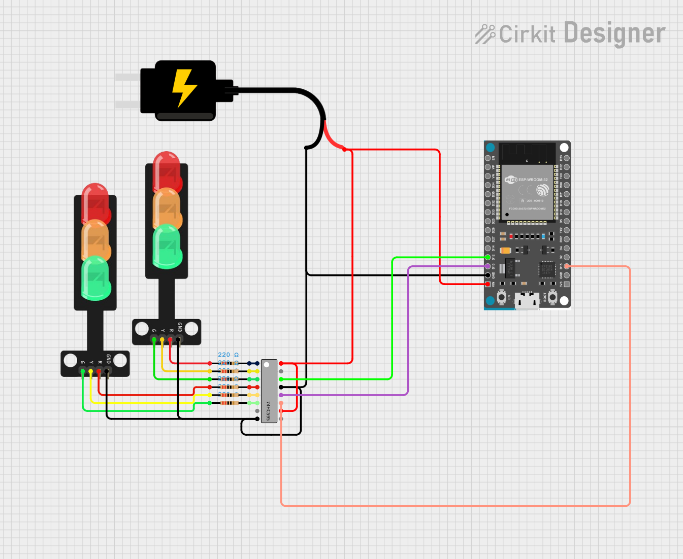
Circuit Documentation
Summary
This circuit is designed to control two traffic lights using an ESP32 microcontroller and a 74HC595 shift register. The traffic lights are connected through resistors to the shift register, which is controlled by the ESP32. A 5V DC power source is used to power the circuit.
Component List
Traffic Light
- Pins: Green, Yellow, Red, GND
- Description: Simulates a traffic light with three LEDs (Green, Yellow, Red).
74HC595 Shift Register
- Pins: Q1, Q2, Q3, Q4, Q5, Q6, Q7, GND, VCC, Q0, DS (DATA), OE (Enable), ST_CP (RCLK), SH_CP (SRCLK), MR (SRCLR), Q7' (QH)
- Description: 8-bit serial-in, serial or parallel-out shift register with output latches.
Resistor (220 Ohms)
- Pins: pin1, pin2
- Description: Limits current to the LEDs in the traffic lights.
DC Source 5V
- Pins: VCC, GND
- Description: Provides 5V DC power to the circuit.
ESP32 Devkit V1
- Pins: 3V3, GND, D15, D2, D4, RX2, TX2, D5, D18, D19, D21, RX0, TX0, D22, D23, EN, VP, VN, D34, D35, D32, D33, D25, D26, D27, D14, D12, D13, VIN
- Description: Microcontroller used to control the shift register and traffic lights.
Wiring Details
Traffic Light 1
- Green: Connected to pin1 of a 220 Ohm resistor.
- Yellow: Connected to pin1 of a 220 Ohm resistor.
- Red: Connected to pin1 of a 220 Ohm resistor.
- GND: Connected to GND of the 5V DC source.
Traffic Light 2
- Green: Connected to pin1 of a 220 Ohm resistor.
- Yellow: Connected to pin1 of a 220 Ohm resistor.
- Red: Connected to pin1 of a 220 Ohm resistor.
- GND: Connected to GND of the 5V DC source.
74HC595 Shift Register
- Q1: Connected to pin2 of a 220 Ohm resistor (Traffic Light 1 Red).
- Q2: Connected to pin2 of a 220 Ohm resistor (Traffic Light 1 Yellow).
- Q3: Connected to pin2 of a 220 Ohm resistor (Traffic Light 1 Green).
- Q4: Connected to pin2 of a 220 Ohm resistor (Traffic Light 2 Red).
- Q5: Connected to pin2 of a 220 Ohm resistor (Traffic Light 2 Yellow).
- Q6: Connected to pin2 of a 220 Ohm resistor (Traffic Light 2 Green).
- GND: Connected to GND of the 5V DC source.
- VCC: Connected to VCC of the 5V DC source.
- DS (DATA): Connected to D12 of the ESP32.
- OE (Enable): Connected to GND of the 5V DC source.
- ST_CP (RCLK): Connected to D13 of the ESP32.
- SH_CP (SRCLK): Connected to D15 of the ESP32.
- MR (SRCLR): Connected to VCC of the 5V DC source.
Resistors (220 Ohms)
- Resistor 1: pin1 connected to Green of Traffic Light 1, pin2 connected to Q3 of 74HC595.
- Resistor 2: pin1 connected to Yellow of Traffic Light 1, pin2 connected to Q2 of 74HC595.
- Resistor 3: pin1 connected to Red of Traffic Light 1, pin2 connected to Q1 of 74HC595.
- Resistor 4: pin1 connected to Green of Traffic Light 2, pin2 connected to Q6 of 74HC595.
- Resistor 5: pin1 connected to Yellow of Traffic Light 2, pin2 connected to Q5 of 74HC595.
- Resistor 6: pin1 connected to Red of Traffic Light 2, pin2 connected to Q4 of 74HC595.
DC Source 5V
- VCC: Connected to VCC of the 74HC595 and VIN of the ESP32.
- GND: Connected to GND of the 74HC595, GND of the ESP32, and GND of both Traffic Lights.
ESP32 Devkit V1
- VIN: Connected to VCC of the 5V DC source.
- GND: Connected to GND of the 5V DC source.
- D12: Connected to DS (DATA) of the 74HC595.
- D13: Connected to ST_CP (RCLK) of the 74HC595.
- D15: Connected to SH_CP (SRCLK) of the 74HC595.
Documented Code
ESP32 Devkit V1 Code
int latchPin = 13;  // ST_CP
int clockPin = 15;  // SH_CP
int dataPin = 12;   // DS

void setup() {
  pinMode(dataPin, OUTPUT);
  pinMode(clockPin, OUTPUT);
  pinMode(latchPin, OUTPUT);

  Serial.begin(9600);
  Serial.print("Start...");
  setSwitch(B00000000);
}

void setSwitch(byte status) {
  digitalWrite(latchPin, LOW);
  shiftOut(dataPin, clockPin, MSBFIRST, status);
  digitalWrite(latchPin, HIGH);
}

void loop() {
  setSwitch(B01001000);
  delay(1000);
  setSwitch(B10110111);
  delay(1000);
}
74HC595 Shift Register Code
void setup() {
  // put your setup code here, to run once:

}

void loop() {
  // put your main code here, to run repeatedly:

}
DC Source 5V Code
void setup() {
  // put your setup code here, to run once:

}

void loop() {
  // put your main code here, to run repeatedly:

}
This documentation provides a comprehensive overview of the circuit, including a summary, detailed component list, wiring details, and documented code for the microcontrollers.