Arduino UNO R4 WiFi Controlled I2C LCD Display with LDR Sensor
Circuit Documentation
Summary of the Circuit
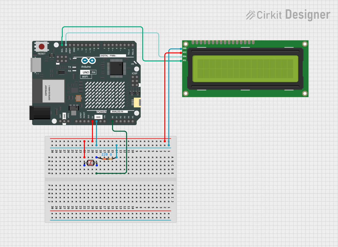
This circuit consists of an Arduino UNO R4 WiFi microcontroller, an I2C LCD 16x2 screen, a photocell (LDR), and a resistor. The Arduino UNO R4 WiFi is the central processing unit of the circuit, responsible for controlling the LCD screen and reading the analog value from the photocell. The I2C LCD screen is used to display information, and the photocell is used to detect the intensity of light. The resistor is used to form a voltage divider with the photocell, which allows the Arduino to read the light levels as an analog voltage.
Component List
I2C LCD 16x2 Screen
- Description: A 16x2 character LCD display that uses the I2C communication protocol.
- Pins: SCL, SDA, VCC (5V), GND, VDD, VO, RS, RW, E, D0, D1, D2, D3, D4, D5, D6, D7, BLA, BLK
Arduino UNO R4 WiFi
- Description: A microcontroller board based on the ATmega328P with built-in WiFi capability.
- Pins: OFF, GND, VRTC, IIC0_SCL, IIC0_SDA, 3V3, GPIO 41, GPIO 0, GPIO 42, GPIO 43, GPIO 44, BOOT, IOREF, RESET, 5V, VIN, A0, A1, A2, A3, A4, A5, RSPCKA, CIPO, COPI, D0/RX, D1/TX, D2, D3, D4, D5, D6, D7, D8, D9, D10, D11, D12, D13, AREF, SDA, SCL
Photocell (LDR)
- Description: A light-dependent resistor whose resistance changes with light intensity.
- Pins: pin 0, pin 1
Resistor
- Description: A passive two-terminal electrical component that implements electrical resistance as a circuit element.
- Resistance: 220 Ohms
- Pins: pin1, pin2
Wiring Details
I2C LCD 16x2 Screen
- SCL: Connected to SCL on Arduino UNO R4 WiFi
- SDA: Connected to SDA on Arduino UNO R4 WiFi
- VCC (5V): Connected to 5V on Arduino UNO R4 WiFi
- GND: Connected to GND on Arduino UNO R4 WiFi
Arduino UNO R4 WiFi
- 5V: Provides power to the I2C LCD 16x2 Screen and Photocell (LDR)
- GND: Common ground for I2C LCD 16x2 Screen and Resistor
- A0: Reads the analog voltage from the voltage divider formed by the Photocell (LDR) and Resistor
- SCL: Connected to SCL on I2C LCD 16x2 Screen
- SDA: Connected to SDA on I2C LCD 16x2 Screen
Photocell (LDR)
- pin 0: Connected to 5V on Arduino UNO R4 WiFi
- pin 1: Connected to one end of the Resistor and A0 on Arduino UNO R4 WiFi
Resistor
- pin1: Connected to pin 1 on Photocell (LDR) and A0 on Arduino UNO R4 WiFi
- pin2: Connected to GND on Arduino UNO R4 WiFi
Documented Code
void setup() {
  // put your setup code here, to run once:

}

void loop() {
  // put your main code here, to run repeatedly:

}
File: sketch.ino
Note: The provided code is a template and does not include specific functionality. It should be expanded to initialize the I2C communication with the LCD screen, read the analog value from the photocell, and display the corresponding information on the LCD.