
Circuit Documentation
Summary
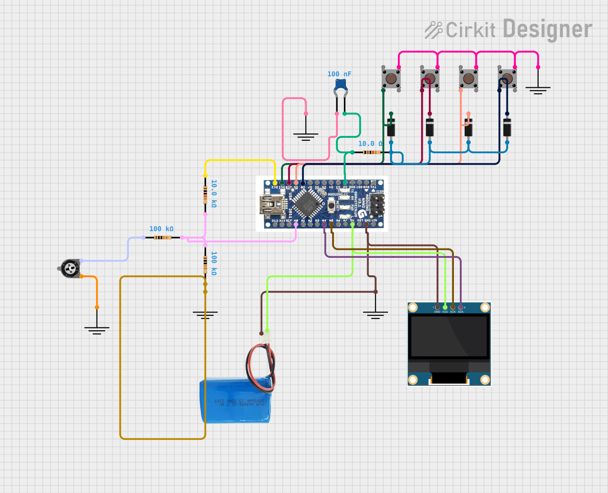
The circuit in question appears to be a microcontroller-based system utilizing an Arduino Nano as the central processing unit. The circuit includes various passive components such as resistors and capacitors, input devices like pushbuttons, and output devices such as an OLED display. Diodes are used, possibly for protection or rectification purposes. The circuit is powered by a 5V battery, and the Arduino Nano regulates the voltage for the OLED display. The circuit also features a trimmer potentiometer, which may be used for adjusting a voltage or setting a reference level.
Component List
Microcontroller
- Arduino Nano: A compact microcontroller board based on the ATmega328P, featuring digital and analog I/O pins.
Passive Components
- Resistors: Components used to limit current or divide voltages in the circuit. Values used in the circuit are 10 Ohms, 10 kOhms, and 100 kOhms.
- Ceramic Capacitor: A non-polarized capacitor with a capacitance of 0.1 µF, likely used for noise filtering or decoupling.
- Trimmer Potentiometer: A variable resistor with a 10 kOhm resistance, used for adjusting levels within the circuit.
Input Devices
- Pushbuttons: Momentary switches that likely serve as user inputs to the microcontroller.
Output Devices
- 0.96" OLED: A small display screen for visual output, interfaced with the Arduino Nano via I2C communication.
Protection Components
- Diodes: Semiconductor devices that allow current to flow in one direction, used for protecting the circuit from reverse voltage or for signal rectification.
Power Supply
- 5V Battery: Provides the power required for the circuit operation.
Ground References
- GND: Ground reference points used to complete the circuit's return paths.
Wiring Details
Arduino Nano
- D12: Connected to a 10 kOhm resistor.
- D11: Connected to the cathode of a diode and a pushbutton.
- D10: Connected to a pushbutton and the cathode of another diode.
- D9: Connected to a pushbutton and the cathode of another diode.
- D8: Connected to a pushbutton and the cathode of another diode.
- D2: Connected to a 10 Ohm resistor and a ceramic capacitor.
- A0: Connected to a network of 10 kOhm, 100 kOhm, and 100 kOhm resistors.
- A4 (SDA): Connected to the SDA pin of the OLED display.
- A5 (SCK): Connected to the SCK pin of the OLED display.
- 5V: Connected to the VDD pin of the OLED display and the positive terminal of the 5V battery.
- GND: Connected to the ground reference points, the GND pin of the OLED display, and the negative terminal of the 5V battery.
Resistors
- 10 Ohm Resistor: Connected between Arduino Nano D2 and a ceramic capacitor.
- 10 kOhm Resistors: One connected between Arduino Nano D12 and another in a network connected to Arduino Nano A0.
- 100 kOhm Resistors: Two in a network connected to Arduino Nano A0.
Ceramic Capacitor
- 0.1 µF Capacitor: Connected between Arduino Nano D2 and ground.
Trimmer Potentiometer
- 10 kOhm Potentiometer: One leg connected to ground, the other to a 100 kOhm resistor.
Pushbuttons
- Each pushbutton has one pin connected to an Arduino Nano digital pin (D11, D10, D9, D8) and another pin connected to the cathode of a diode. The third pin of each pushbutton is connected to ground.
Diodes
- The anodes of all diodes are connected together and to a 10 Ohm resistor. The cathodes are connected to pushbuttons and Arduino Nano digital pins (D11, D10, D9, D8).
OLED Display
- SDA: Connected to Arduino Nano A4.
- SCK: Connected to Arduino Nano A5.
- VDD: Connected to Arduino Nano 5V.
- GND: Connected to ground.
Power Supply
- 5V Battery: Positive terminal connected to Arduino Nano 5V and negative terminal connected to ground.
Documented Code
No code was provided for the microcontroller. In a typical application, the code would initialize the input/output pins, handle the pushbutton presses, manage the OLED display via the I2C interface, and perform any other required logic functions.