
ESP32-Based Smart Power Monitoring and Control System with OLED Display
View and Edit Project In Cirkit Designer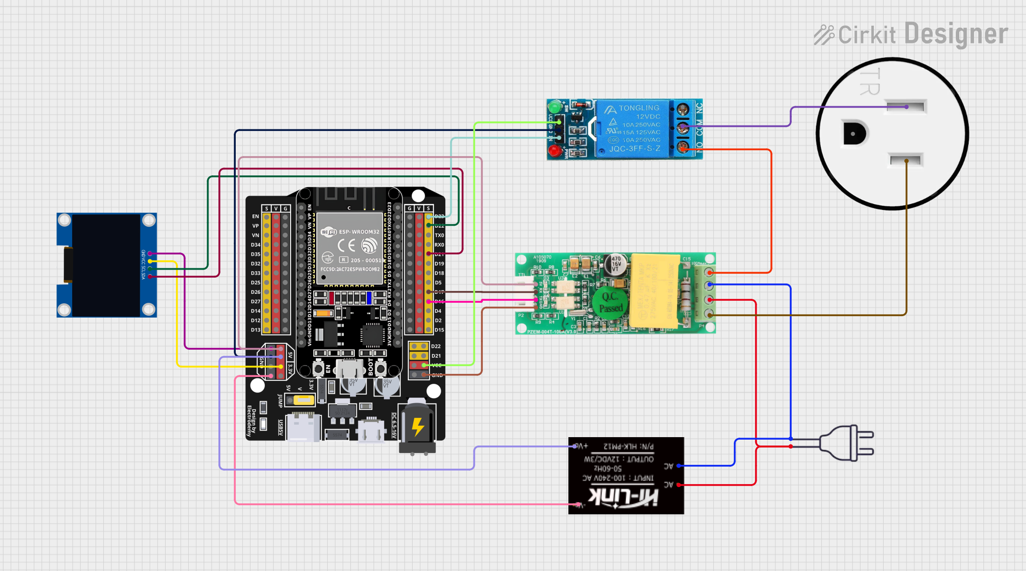
Circuit Documentation
Summary
This document provides a detailed overview of a circuit design that includes various components such as an ESP32 Expansion Board, a 12V Single Channel Relay, a 128x64 OLED Display, a PZEM004t power monitor, an HLK-PM12 power module, a 120V Outlet, and a 220V power source. The document includes a component list, wiring details, and code documentation.
Component List
HLK-PM12
- Description: Power module
- Pins: +V0, -V0, AC
- Purpose: Converts AC to DC power for the circuit.
PZEM004t
- Description: Power monitor
- Pins: VCC, RX, TX, GND, IN, OUT
- Purpose: Monitors power consumption and provides data to the ESP32.
ESP32 - Expansion Board
- Description: Microcontroller board
- Pins: +, -, EN, VP, VN, D34, D32, D33, D25, D26, D27, D14, D12, D13, D23, D22, TX0, RX0, D21, D19, D18, D5, D17, D16, D4, D2, D15, VCC, G, 5V, 3.3V, V
- Purpose: Central processing unit for the circuit, controlling other components and processing data.
Power 220V
- Description: 220V AC power source
- Pins: Hot wire, Neutral wire
- Purpose: Provides AC power to the circuit.
120V Outlet
- Description: Standard 120V AC outlet
- Pins: AC Neutral, AC Hot, GND
- Purpose: Provides an AC outlet for connecting devices.
12V Single Channel Relay
- Description: Relay module
- Pins: NC, COM, NO, IN, GND, VCC
- Purpose: Controls high voltage devices using a low voltage signal from the ESP32.
128x64 OLED Display (I2C IIC SPI Serial)
- Description: OLED display module
- Pins: GND, SDA, SCL, VCC
- Purpose: Displays information from the ESP32.
Wiring Details
HLK-PM12
- +V0 connected to ESP32 - Expansion Board 5V
- -V0 connected to ESP32 - Expansion Board G
- AC connected to PZEM004t IN and Power 220V hot wire
- AC connected to PZEM004t IN and Power 220V neutral wire
PZEM004t
- VCC connected to ESP32 - Expansion Board 5V
- RX connected to ESP32 - Expansion Board D17
- TX connected to ESP32 - Expansion Board D16
- GND connected to ESP32 - Expansion Board G
- IN connected to HLK-PM12 AC and Power 220V hot wire
- IN connected to HLK-PM12 AC and Power 220V neutral wire
- OUT connected to 12V Single Channel Relay NO
- OUT connected to 120V Outlet AC Hot
ESP32 - Expansion Board
- D23 connected to 12V Single Channel Relay IN
- D22 connected to 128x64 OLED Display SCL
- D21 connected to 128x64 OLED Display SDA
- D17 connected to PZEM004t RX
- D16 connected to PZEM004t TX
- VCC connected to 12V Single Channel Relay VCC
- G connected to PZEM004t GND
- 5V connected to PZEM004t VCC
- 5V connected to HLK-PM12 +V0
- 3.3V connected to 128x64 OLED Display VCC
- G connected to 128x64 OLED Display GND
- G connected to 12V Single Channel Relay GND
- G connected to HLK-PM12 -V0
Power 220V
- Hot wire connected to HLK-PM12 AC and PZEM004t IN
- Neutral wire connected to HLK-PM12 AC and PZEM004t IN
120V Outlet
- AC Neutral connected to 12V Single Channel Relay COM
- AC Hot connected to PZEM004t OUT
12V Single Channel Relay
- NC not connected
- COM connected to 120V Outlet AC Neutral
- NO connected to PZEM004t OUT
- IN connected to ESP32 - Expansion Board D23
- GND connected to ESP32 - Expansion Board G
- VCC connected to ESP32 - Expansion Board VCC
128x64 OLED Display (I2C IIC SPI Serial)
- GND connected to ESP32 - Expansion Board G
- SDA connected to ESP32 - Expansion Board D21
- SCL connected to ESP32 - Expansion Board D22
- VCC connected to ESP32 - Expansion Board 3.3V
Code Documentation
No code is provided for this circuit.
This document provides a comprehensive overview of the circuit, including a detailed component list and wiring details. Each component is described, and its connections are clearly outlined to ensure proper assembly and functionality.