
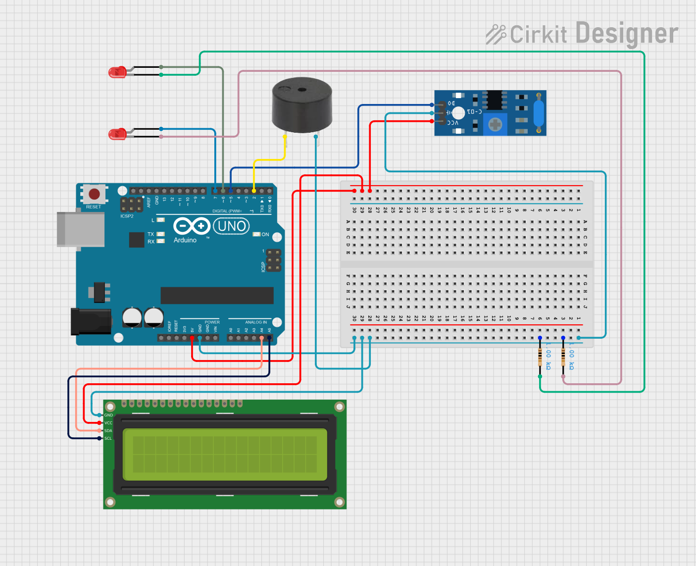
Circuit Documentation
Summary
This circuit involves an Arduino UNO microcontroller interfacing with various components including a 16x2 I2C LCD, a buzzer, an SW-420 vibration sensor, and two red LEDs. The circuit is designed to demonstrate basic input and output operations, such as displaying information on an LCD, detecting vibrations, and controlling LEDs and a buzzer.
Component List
Arduino UNO
- Description: A microcontroller board based on the ATmega328P.
- Pins: UNUSED, IOREF, Reset, 3.3V, 5V, GND, Vin, A0, A1, A2, A3, A4, A5, SCL, SDA, AREF, D13, D12, D11, D10, D9, D8, D7, D6, D5, D4, D3, D2, D1, D0
16x2 I2C LCD
- Description: A 16x2 character LCD display with I2C interface.
- Pins: GND, VCC, SDA, SCL
Buzzer
- Description: A simple piezoelectric buzzer.
- Pins: PIN, GND
SW-420 Vibration Sensor
- Description: A vibration sensor module.
- Pins: vcc, Ground, Digital output
LED: Two Pin (red)
- Description: A standard red LED.
- Pins: cathode, anode
Resistor (1k Ohms)
- Description: A resistor with a resistance of 1000 Ohms.
- Pins: pin1, pin2
Wiring Details
Arduino UNO
- GND: Connected to GND of the SW-420 Vibration Sensor, Resistor (both instances), Buzzer, and 16x2 I2C LCD.
- 5V: Connected to vcc of the SW-420 Vibration Sensor and VCC of the 16x2 I2C LCD.
- A4: Connected to SDA of the 16x2 I2C LCD.
- A5: Connected to SCL of the 16x2 I2C LCD.
- D7: Connected to anode of the first red LED.
- D6: Connected to anode of the second red LED.
- D5: Connected to Digital output of the SW-420 Vibration Sensor.
- D2: Connected to PIN of the Buzzer.
16x2 I2C LCD
- GND: Connected to GND of the Arduino UNO.
- VCC: Connected to 5V of the Arduino UNO.
- SDA: Connected to A4 of the Arduino UNO.
- SCL: Connected to A5 of the Arduino UNO.
Buzzer
- PIN: Connected to D2 of the Arduino UNO.
- GND: Connected to GND of the Arduino UNO.
SW-420 Vibration Sensor
- Ground: Connected to GND of the Arduino UNO.
- vcc: Connected to 5V of the Arduino UNO.
- Digital output: Connected to D5 of the Arduino UNO.
LED: Two Pin (red)
- First LED:
- anode: Connected to D7 of the Arduino UNO.
- cathode: Connected to pin2 of the first Resistor.
- Second LED:
- anode: Connected to D6 of the Arduino UNO.
- cathode: Connected to pin2 of the second Resistor.
Resistor (1k Ohms)
- First Resistor:
- pin1: Connected to Ground of the SW-420 Vibration Sensor.
- pin2: Connected to cathode of the first red LED.
- Second Resistor:
- pin1: Connected to Ground of the SW-420 Vibration Sensor.
- pin2: Connected to cathode of the second red LED.
Code Documentation
Arduino UNO Code
sketch.ino
void setup() {
  // put your setup code here, to run once:

}

void loop() {
  // put your main code here, to run repeatedly:

}
documentation.txt
(No additional documentation provided)
This documentation provides a comprehensive overview of the circuit, including a detailed list of components, their wiring connections, and the code used in the Arduino UNO microcontroller.