Cirkit Designer
Your all-in-one circuit design IDE
Home /
Project Documentation
Battery-Powered LED Circuit with Resistor
Circuit Documentation
Summary
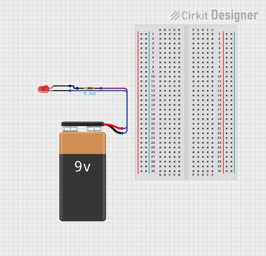
This document provides a detailed description of a simple LED circuit powered by a 9V battery. The circuit includes a red LED, a resistor, and a 9V battery. The resistor is used to limit the current flowing through the LED to prevent it from burning out.
Component List
LED: Two Pin (red)
- Description: A red light-emitting diode (LED) with two pins: anode and cathode.
- Pins:
- anode
- cathode
9V Battery
- Description: A 9V battery used as the power source for the circuit.
- Pins:
- + (positive terminal)
- - (negative terminal)
Resistor
- Description: A resistor used to limit the current flowing through the LED.
- Pins:
- pin1
- pin2
- Properties:
- Resistance: 200 Ohms
Wiring Details
LED: Two Pin (red)
- cathode is connected to the - pin of the 9V Battery.
- anode is connected to pin2 of the Resistor.
9V Battery
- - pin is connected to the cathode of the LED.
- + pin is connected to pin1 of the Resistor.
Resistor
- pin1 is connected to the + pin of the 9V Battery.
- pin2 is connected to the anode of the LED.
Code
There is no microcontroller code associated with this circuit.
This document provides a comprehensive overview of the components and wiring details for the LED circuit. The resistor ensures that the LED operates safely within its current rating, and the 9V battery provides the necessary power for the circuit.