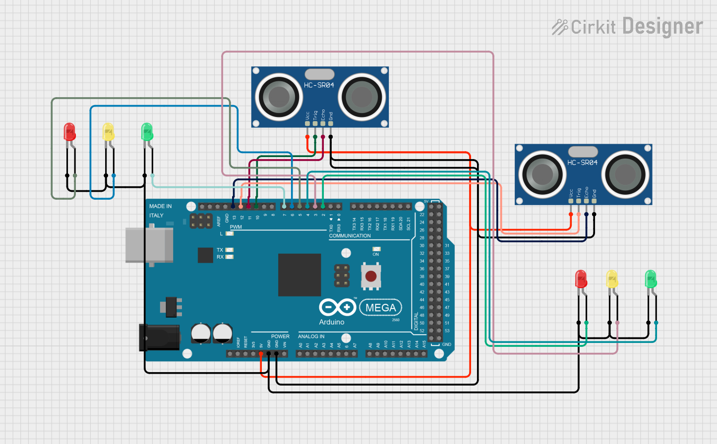
Arduino Mega 2560 Based Ultrasonic Distance Measurement with LED Indicators

Circuit Documentation
Summary
The circuit in question is designed around the Arduino Mega 2560 microcontroller and includes a variety of components such as HC-SR04 Ultrasonic Sensors and LEDs of different colors (red, green, and yellow). The Arduino Mega 2560 is responsible for controlling the LEDs and reading distance measurements from the ultrasonic sensors. The LEDs are used as indicators, and their operation is controlled via PWM pins on the Arduino. The ultrasonic sensors are powered by the 5V output from the Arduino and are interfaced with digital pins for triggering and echo reception.
Component List
Arduino Mega 2560
- Microcontroller board based on the ATmega2560
- It has 54 digital input/output pins (of which 15 can be used as PWM outputs), 16 analog inputs, 4 UARTs (hardware serial ports), a 16 MHz crystal oscillator, a USB connection, a power jack, an ICSP header, and a reset button.
HC-SR04 Ultrasonic Sensor
- Ultrasonic distance measuring module
- Uses sonar to determine the distance to an object
- Features a set of ultrasonic transmitter and receiver
LED: Two Pin (red)
- Standard red LED
- Has an anode and cathode for simple on/off control
LED: Two Pin (green)
- Standard green LED
- Has an anode and cathode for simple on/off control
LED: Two Pin (yellow)
- Standard yellow LED
- Has an anode and cathode for simple on/off control
Wiring Details
Arduino Mega 2560
- 5V pin connected to the VCC pins of both HC-SR04 Ultrasonic Sensors
- GND pin connected to the GND pins of both HC-SR04 Ultrasonic Sensors and the cathodes of all LEDs
- D2 PWM pin connected to the anode of one red LED
- D3 PWM pin connected to the anode of one yellow LED
- D4 PWM pin connected to the anode of one green LED
- D5 PWM pin connected to the anode of another red LED
- D6 PWM pin connected to the anode of another yellow LED
- D7 PWM pin connected to the anode of another green LED
- D10 PWM pin connected to the TRIG pin of one HC-SR04 Ultrasonic Sensor
- D11 PWM pin connected to the ECHO pin of one HC-SR04 Ultrasonic Sensor
- D12 PWM pin connected to the TRIG pin of the other HC-SR04 Ultrasonic Sensor
- D13 PWM pin connected to the ECHO pin of the other HC-SR04 Ultrasonic Sensor
HC-SR04 Ultrasonic Sensor
- VCC pin connected to the 5V output from the Arduino Mega 2560
- GND pin connected to the GND pin on the Arduino Mega 2560
- TRIG pin connected to a digital PWM pin on the Arduino Mega 2560 for triggering the sensor
- ECHO pin connected to a digital PWM pin on the Arduino Mega 2560 to read the echo signal
LEDs (red, green, yellow)
- Cathode (negative) pin connected to the GND pin on the Arduino Mega 2560
- Anode (positive) pin connected to a digital PWM pin on the Arduino Mega 2560 for controlling the LED state
Documented Code
void setup() {
  // put your setup code here, to run once:

}

void loop() {
  // put your main code here, to run repeatedly:

}
The provided code is a template with empty setup() and loop() functions, which are the standard structure for Arduino sketches. The setup() function is intended to contain initialization code that runs once when the microcontroller is powered on or reset. The loop() function is designed to contain the main logic of the program, which runs repeatedly as long as the microcontroller is powered.
Further implementation details would be required to control the LEDs and read from the ultrasonic sensors, which would involve writing to the digital pins connected to the LEDs and implementing pulse timing logic for the ultrasonic sensors.