
ESP8266 NodeMCU Wi-Fi Controlled Smart Home Automation with LCD Display
View and Edit Project In Cirkit Designer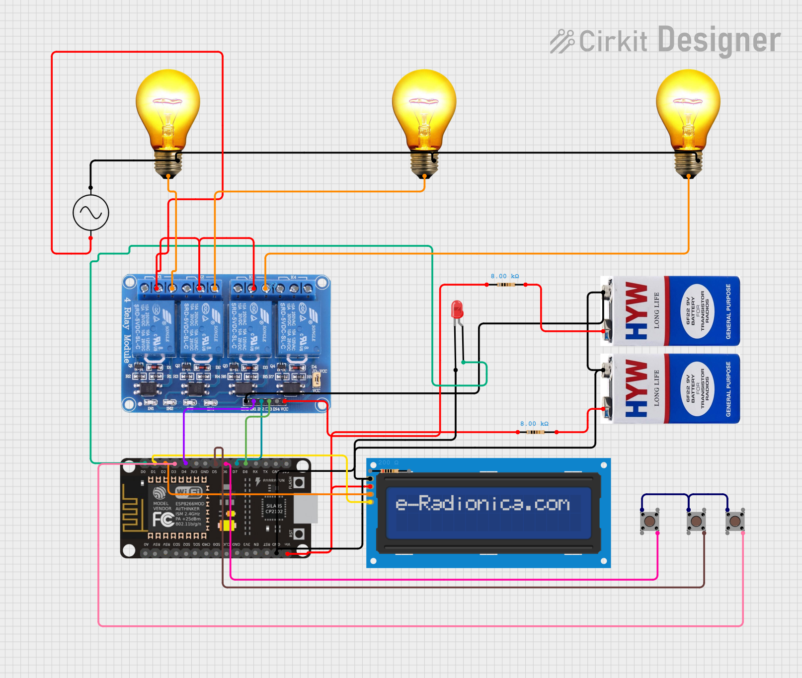
Circuit Documentation
Summary
This circuit is a smart home automation system based on the ESP8266 NodeMCU microcontroller. It includes a 4-channel relay module to control AC bulbs, an LCD screen for displaying status, pushbuttons for manual control, and an LED indicator for WiFi status. The system connects to WiFi and can be controlled remotely using the Sinric Pro platform.
Component List
ESP8266 NodeMCU
- Description: A low-cost WiFi microcontroller with GPIO pins.
- Pins: D0, D1, D2, D3, D4, 3V3, GND, D5, D6, D7, D8, RX, TX, A0, RSV, SD3, SD2, SD1, CMD, SD0, CLK, EN, RST, VIN
Relay 4 Channel 5V
- Description: A relay module to control high voltage devices.
- Pins: GND, IN1, IN2, IN3, IN4, VCC, COM1, COM2, COM3, COM4, NO1, NO2, NO3, NO4, NC1, NC2, NC3, NC4
AC Bulb
- Description: Standard AC bulb.
- Pins: P, N
LCD Screen 16x2 I2C
- Description: A 16x2 character LCD with I2C interface.
- Pins: SCL, SDA, VCC, GND
Pushbutton
- Description: A simple pushbutton switch.
- Pins: Pin 3 (out), Pin 4 (out), Pin 1 (in), Pin 2 (in)
LED: Two Pin (Red)
- Description: A red LED.
- Pins: Cathode, Anode
9V Battery
- Description: A 9V battery for power supply.
- Pins: +, -
Resistor
- Description: A resistor with specified resistance.
- Pins: Pin1, Pin2
- Properties:
- Resistance: 200 Ohms
- Resistance: 8000 Ohms
AC Supply
- Description: AC power supply.
- Pins: +ve, -ve
Wiring Details
ESP8266 NodeMCU
- D0: Connected to the anode of the LED.
- D1: Connected to the SCL pin of the LCD screen.
- D2: Connected to the SDA pin of the LCD screen.
- D3: Connected to Pin 1 (in) of a pushbutton.
- D4: Connected to IN1 of the relay module.
- D5: Connected to Pin 1 (in) of another pushbutton.
- D6: Connected to Pin 1 (in) of another pushbutton.
- D7: Connected to IN2 of the relay module.
- D8: Connected to IN3 of the relay module.
- GND: Connected to the GND of the relay module, cathode of the LED, GND of the LCD screen, and the negative terminal of the 9V battery.
- VIN: Connected to pin1 of an 8000 Ohm resistor and VCC of the LCD screen.
Relay 4 Channel 5V
- GND: Connected to the GND of the ESP8266 NodeMCU and the negative terminal of the 9V battery.
- IN1: Connected to D4 of the ESP8266 NodeMCU.
- IN2: Connected to D7 of the ESP8266 NodeMCU.
- IN3: Connected to D8 of the ESP8266 NodeMCU.
- VCC: Connected to pin1 of an 8000 Ohm resistor.
- COM1, COM2, COM3: Connected to +ve of the AC supply.
- NO1: Connected to P of an AC bulb.
- NO2: Connected to P of another AC bulb.
- NO3: Connected to P of another AC bulb.
AC Bulb
- P: Connected to NO1, NO2, and NO3 of the relay module.
- N: Connected to -ve of the AC supply.
LCD Screen 16x2 I2C
- SCL: Connected to D1 of the ESP8266 NodeMCU.
- SDA: Connected to D2 of the ESP8266 NodeMCU.
- VCC: Connected to pin1 of an 8000 Ohm resistor.
- GND: Connected to the GND of the ESP8266 NodeMCU.
Pushbutton
- Pin 1 (in): Connected to D3, D5, and D6 of the ESP8266 NodeMCU.
- Pin 4 (out): Connected to Pin 4 (out) of other pushbuttons.
LED: Two Pin (Red)
- Anode: Connected to D0 of the ESP8266 NodeMCU.
- Cathode: Connected to the GND of the ESP8266 NodeMCU.
9V Battery
- -: Connected to the GND of the relay module and the ESP8266 NodeMCU.
- +: Connected to pin2 of an 8000 Ohm resistor.
Resistor
- Pin1: Connected to VIN of the ESP8266 NodeMCU and VCC of the LCD screen.
- Pin2: Connected to the positive terminal of the 9V battery.
AC Supply
- +ve: Connected to COM1, COM2, and COM3 of the relay module.
- -ve: Connected to N of the AC bulbs.
Code Documentation
#include <ESP8266WiFi.h>
#include <SinricPro.h>
#include <SinricProSwitch.h>
#include <Wire.h>
#include <LiquidCrystal_I2C.h>

// Replace with your WiFi credentials
#define WIFI_SSID "Galaxy M35 5G BE86"
#define WIFI_PASSWORD "5gpunxb5xsvtwms"

// Replace with your Sinric Pro credentials
#define APP_KEY "16969b32-c75a-4450-9552-bf51f59899e1"
#define APP_SECRET "7740363e-d9eb-454f-a96b-d5bc748696f7-1852fbd7-ea9e-4d6c-b632-ccb39f7c4353"

// Replace with your device IDs from Sinric Pro
#define DEVICE_ID_LOAD1 "6759e87b13f98f1416070b10"  // LOAD 1
#define DEVICE_ID_LOAD2 "67633cee13f98f14160e8732"  // LOAD 2
#define DEVICE_ID_LOAD3 "6759e91213f98f1416070bfd"  // LOAD 3

// Pin definitions for the relays (use safer GPIO pins)
#define RELAY_1_PIN 2  // GPIO D4
#define RELAY_2_PIN 15 // GPIO D8
#define RELAY_3_PIN 13 // GPIO D7

// Pin definitions for push buttons
#define BUTTON_1_PIN 12 // GPIO D6
#define BUTTON_2_PIN 14 // GPIO D5
#define BUTTON_3_PIN 0  // GPIO D3

// Pin for WiFi connection LED
#define WIFI_LED_PIN 16 // GPIO D0 (common LED pin)

// LCD display address (change if needed)
LiquidCrystal_I2C lcd(0x27, 16, 2);  // 16x2 LCD

bool relay1State = false;
bool relay2State = false;
bool relay3State = false;

bool lastWifiState = false;

// Variables for periodic display update
unsigned long lastDisplayUpdate = 0;  // Tracks last LCD update time
unsigned int currentLoadToDisplay = 1;  // Tracks the current load being displayed
unsigned long displayInterval = 2000;  // Interval (ms) to show each load

// Callback function to handle relay states from Sinric Pro
bool onPowerState(const String &deviceId, bool &state) {
  if (deviceId == DEVICE_ID_LOAD1) {
    digitalWrite(RELAY_1_PIN, state ? LOW : HIGH); // Active LOW relay control
    relay1State = state;
  } else if (deviceId == DEVICE_ID_LOAD2) {
    digitalWrite(RELAY_2_PIN, state ? LOW : HIGH);
    relay2State = state;
  } else if (deviceId == DEVICE_ID_LOAD3) {
    digitalWrite(RELAY_3_PIN, state ? LOW : HIGH);
    relay3State = state;
  }
  return true; // Action handled
}

void setup() {
  Serial.begin(9600);

  // Set relay pins as output and turn them off initially
  pinMode(RELAY_1_PIN, OUTPUT);
  pinMode(RELAY_2_PIN, OUTPUT);
  pinMode(RELAY_3_PIN, OUTPUT);
  digitalWrite(RELAY_1_PIN, HIGH);
  digitalWrite(RELAY_2_PIN, HIGH);
  digitalWrite(RE