
Arduino UNO Light-Tracking Servo System with Dual Photocells
View and Edit Project In Cirkit Designer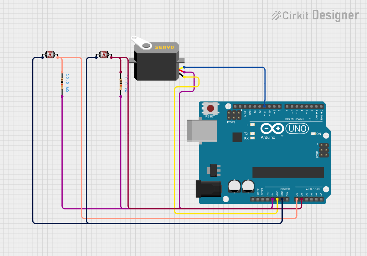
Circuit Documentation
Summary
This circuit is designed to control a servo motor based on the readings from two Light Dependent Resistors (LDRs). The Arduino UNO microcontroller reads the analog values from the LDRs and adjusts the position of the servo motor accordingly. The circuit includes power connections, ground connections, and signal connections to ensure proper functionality.
Component List
Arduino UNO
- Description: A microcontroller board based on the ATmega328P.
- Pins: UNUSED, IOREF, Reset, 3.3V, 5V, GND, Vin, A0, A1, A2, A3, A4, A5, SCL, SDA, AREF, D13, D12, D11, D10, D9, D8, D7, D6, D5, D4, D3, D2, D1, D0
Servo
- Description: A servo motor used for precise control of angular position.
- Pins: gnd, vcc, pulse
Photocell (LDR)
- Description: A light-dependent resistor used to measure light intensity.
- Pins: pin 0, pin 1
Photocell (LDR)
- Description: A light-dependent resistor used to measure light intensity.
- Pins: pin 0, pin 1
Resistor (10k Ohms)
- Description: A resistor with a resistance of 10k Ohms.
- Pins: pin1, pin2
Resistor (10k Ohms)
- Description: A resistor with a resistance of 10k Ohms.
- Pins: pin1, pin2
Wiring Details
Arduino UNO
5V
- Connected to:
- Resistor pin2
- Resistor pin2
- Servo vcc
- Connected to:
GND
- Connected to:
- Servo gnd
- Photocell (LDR) pin 0
- Photocell (LDR) pin 0
- Connected to:
A0
- Connected to:
- Photocell (LDR) pin 1
- Resistor pin1
- Connected to:
A1
- Connected to:
- Resistor pin1
- Photocell (LDR) pin 1
- Connected to:
D11
- Connected to:
- Servo pulse
- Connected to:
Servo
gnd
- Connected to:
- Arduino UNO GND
- Connected to:
vcc
- Connected to:
- Arduino UNO 5V
- Connected to:
pulse
- Connected to:
- Arduino UNO D11
- Connected to:
Photocell (LDR) 1
pin 0
- Connected to:
- Arduino UNO GND
- Connected to:
pin 1
- Connected to:
- Arduino UNO A0
- Resistor pin1
- Connected to:
Photocell (LDR) 2
pin 0
- Connected to:
- Arduino UNO GND
- Connected to:
pin 1
- Connected to:
- Arduino UNO A1
- Resistor pin1
- Connected to:
Resistor 1 (10k Ohms)
pin1
- Connected to:
- Photocell (LDR) pin 1
- Arduino UNO A0
- Connected to:
pin2
- Connected to:
- Arduino UNO 5V
- Connected to:
Resistor 2 (10k Ohms)
pin1
- Connected to:
- Photocell (LDR) pin 1
- Arduino UNO A1
- Connected to:
pin2
- Connected to:
- Arduino UNO 5V
- Connected to:
Code Documentation
#include <Servo.h>

// Define the LDR sensor pins
#define LDR1 A0
#define LDR2 A1

// Define the error value. You can change it as you like
#define error 10

// Starting point of the servo motor
int Spoint =  90;

// Create an object for the servo motor
Servo servo;

void setup() {
  // Include servo motor PWM pin
  servo.attach(11);
  // Set the starting point of the servo
  servo.write(Spoint);
  delay(1000);
}

void loop() {
  // Get the LDR sensor value
  int ldr1 = analogRead(LDR1);
  // Get the LDR sensor value
  int ldr2 = analogRead(LDR2);

  // Get the difference of these values
  int value1 = abs(ldr1 - ldr2);
  int value2 = abs(ldr2 - ldr1);

  // Check these values using a IF condition
  if ((value1 <= error) || (value2 <= error)) {

  } else {
    if (ldr1 > ldr2) {
      Spoint = --Spoint;
    }
    if (ldr1 < ldr2) {
      Spoint = ++Spoint;
    }
  }
  // Write values on the servo motor
  servo.write(Spoint);
  delay(80);
}
This code reads the values from two LDR sensors connected to analog pins A0 and A1 of the Arduino UNO. It then compares the values and adjusts the position of the servo motor connected to digital pin 11 based on the difference between the two LDR readings. The servo motor's position is updated in small increments to ensure smooth movement.