
ESP32-Based Battery-Powered Hyperhidrosis Treatment Device with OLED Display
View and Edit Project In Cirkit Designer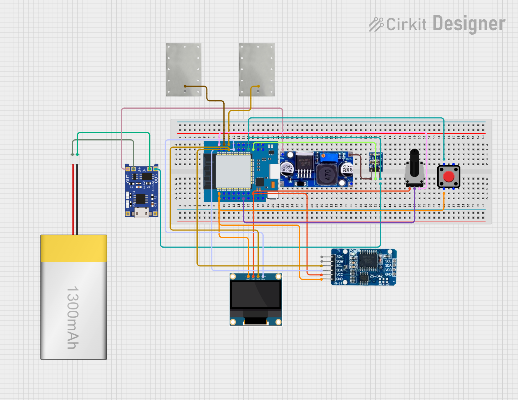
Circuit Documentation
Summary
This document provides a detailed overview of a circuit designed for hyperhidrosis treatment. The circuit includes an ESP32 microcontroller, an OLED display, a real-time clock (RTC), a rotary potentiometer, a pushbutton, a LiPoly battery, a TP4056 battery charger, an LM2596 voltage regulator, and an AMS1117 3.3V voltage regulator. The circuit is designed to control the current flow to electrodes for a specified treatment duration, with user input for current adjustment and session control.
Component List
0.96" OLED
- Description: OLED display module
- Pins: GND, VDD, SCK, SDA
TP4056
- Description: Lithium battery charger module
- Pins: OUT-, B-, B+, OUT+, IN-, IN+
LiPoly Battery (1300mAh)
- Description: Rechargeable lithium polymer battery
- Pins: positive, negative
RTC DS3231
- Description: Real-time clock module
- Pins: 32K, SQW, SCL, SDA, VCC, GND
LM2596
- Description: DC-DC buck converter
- Pins: IN, OUT
AMS1117 3.3
- Description: 3.3V voltage regulator
- Pins: VIN, OUT, GND
Rotary Potentiometer
- Description: Variable resistor for adjusting current
- Pins: leg1, wiper, leg2
- Properties: Resistance: 10000 Ohms
Red Pushbutton
- Description: Pushbutton switch for session control
- Pins: Pin 2, Pin 1, Pin 3, Pin 4
Aluminum Sheet
- Description: Electrode for current flow
- Pins: -, +
ESP32 Mini
- Description: Microcontroller with Wi-Fi and Bluetooth capabilities
- Pins: GND, GPIO27, GPIO25, GPIO32, TDI, GPIO4, GPIO0, GPIO2, SD1, CLK, RXD, TXD, GPIO22, GPIO21, GPIO17, GPIO16, VCC, TD0, SD0, RST, SVP, GPIO26, GPIO18, GPIO19, GPIO23, GPIO5, 3.3V, TCK, SD3, NC, SVN, GPIO35, GPIO33, GPIO34, TMS, SD2
Wiring Details
0.96" OLED
- GND: Connected to GND of ESP32 Mini, RTC DS3231, and Red Pushbutton
- VDD: Connected to 3.3V of ESP32 Mini
- SCK: Connected to GPIO22 of ESP32 Mini and SCL of RTC DS3231
- SDA: Connected to GPIO21 of ESP32 Mini and SDA of RTC DS3231
TP4056
- OUT-: Connected to GND of ESP32 Mini, ams1117 3.3, and Red Pushbutton
- B-: Connected to negative of LiPoly Battery
- B+: Connected to positive of LiPoly Battery
- OUT+: Connected to IN of LM2596
LiPoly Battery (1300mAh)
- positive: Connected to B+ of TP4056
- negative: Connected to B- of TP4056
RTC DS3231
- GND: Connected to GND of ESP32 Mini, 0.96" OLED, and Red Pushbutton
- VCC: Connected to 3.3V of ESP32 Mini
- SCL: Connected to GPIO22 of ESP32 Mini and SCK of 0.96" OLED
- SDA: Connected to GPIO21 of ESP32 Mini and SDA of 0.96" OLED
LM2596
- IN: Connected to OUT+ of TP4056
- OUT: Connected to VIN of ams1117 3.3
AMS1117 3.3
- VIN: Connected to OUT of LM2596
- OUT: Connected to GPIO2 and VCC of ESP32 Mini
- GND: Connected to GND of ESP32 Mini, TP4056, and Red Pushbutton
Rotary Potentiometer
- leg1: Connected to 3.3V of ESP32 Mini
- wiper: Connected to GPIO34 of ESP32 Mini
- leg2: Connected to GND and TXD of ESP32 Mini
Red Pushbutton
- Pin 1: Connected to GND of ESP32 Mini, TP4056, and ams1117 3.3
- Pin 2: Connected to RST and GND of ESP32 Mini, and GND of 0.96" OLED and RTC DS3231
Aluminum Sheet
- +: Connected to GPIO27 and RXD of ESP32 Mini
- -: Not connected
ESP32 Mini
- GND: Connected to GND of 0.96" OLED, RTC DS3231, Red Pushbutton, Rotary Potentiometer, and TP4056
- 3.3V: Connected to VDD of 0.96" OLED, VCC of RTC DS3231, and leg1 of Rotary Potentiometer
- GPIO27: Connected to + of Aluminum Sheet
- GPIO25: Connected to GPIO22 of ESP32 Mini, SCK of 0.96" OLED, and SCL of RTC DS3231
- GPIO32: Connected to GPIO21 of ESP32 Mini, SDA of 0.96" OLED, and SDA of RTC DS3231
- GPIO34: Connected to wiper of Rotary Potentiometer
- GPIO0: Connected to GND of ams1117 3.3 and Red Pushbutton
- GPIO2: Connected to OUT of ams1117 3.3
- GPIO22: Connected to GPIO25 of ESP32 Mini, SCK of 0.96" OLED, and SCL of RTC DS3231
- GPIO21: Connected to GPIO32 of ESP32 Mini, SDA of 0.96" OLED, and SDA of RTC DS3231
- GPIO23: Connected to GPIO34 of ESP32 Mini and wiper of Rotary Potentiometer
- GPIO26: Connected to SVN of ESP32 Mini
- GPIO18: Connected to GPIO35 of ESP32 Mini
- GPIO19: Connected to GPIO33 of ESP32 Mini
- GPIO5: Connected to TMS of ESP32 Mini
- TDI: Connected to GPIO17 of ESP32 Mini
- GPIO4: Connected to GPIO16 of ESP32 Mini
- SD1: Connected to TD0 of ESP32 Mini
- CLK: Connected to SD0 of ESP32 Mini
- SVP: Connected to NC of ESP32 Mini
- TCK: Connected to SD2 of ESP32 Mini
- SD3: Connected to NC of ESP32 Mini
Code Documentation
#include <Wire.h>
#include <Adafruit_GFX.h>
#include <Adafruit_SSD1306.h>
#include <RTClib.h>

// Pin Definitions
#define POT_PIN 34
#define BUTTON_PIN 0
#define ELECTRODE_PIN_POS 25 // Positive electrode
#define ELECTRODE_PIN_NEG 26 // Negative electrode
#define BATTERY_PIN 35

// OLED Display
#define SCREEN_WIDTH 128
#define SCREEN_HEIGHT 64
Adafruit_SSD1306 display(SCREEN_WIDTH, SCREEN_HEIGHT, &Wire, -1);

// RTC
RTC_DS3231 rtc;

// Variables
int sessionTime = 600; // 10 minutes session
int currentFlow = 0;
bool sessionActive = false;
unsigned long startTime;
unsigned long currentTime;

void setup() {
  // Initialize Serial
  Serial.begin(115200);

  // Initialize OLED
  if (!display.begin(SSD1306_I2C_ADDRESS, OLED_RESET)) {
    Serial.println(F("SSD1306 allocation failed"));
    for (;;);
  }
  display.display();
  delay(2000);
  display.clearDisplay();

  // Initialize RTC
  if (!rtc.begin()) {
    Serial.println("Couldn't find RTC");
    while (1);
  }

  // Initialize Pins
  pinMode(POT_PIN, INPUT);
  pinMode(BUTTON_PIN, INPUT_PULLUP);
  pinMode(ELECTRODE_PIN_POS, OUTPUT);
  pinMode(ELECTRODE_PIN_NEG, OUTPUT);
  pinMode(BATTERY_PIN, INPUT);

  // Setup PWM channels
  const int freq = 5000;
  const int ledChannel = 0;
  const int resolution = 8;
  ledcSetup(ledChannel, freq, resolution);
  ledcAttachPin(ELECTRODE_PIN_POS, ledChannel);

  // Display initial message
  display.setTextSize(1);
  display.setTextColor(SSD1306_WHITE);
  display.setCursor(0, 0);
  display.println