
ESP32-Controlled Robotics Interface with Dual DC Motors, Servos, RFID, and LCD Display
View and Edit Project In Cirkit Designer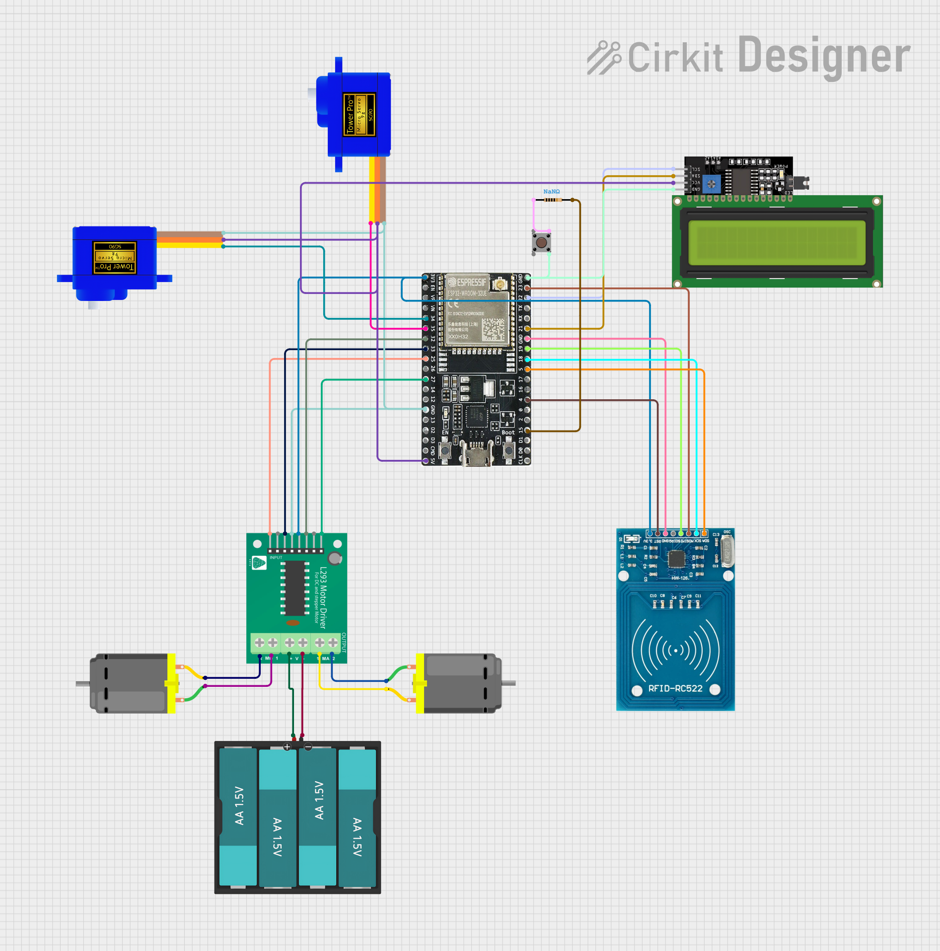
Circuit Documentation
Summary
This circuit is designed to control two DC motors using an L293D motor driver, interfaced with an ESP32 microcontroller. The circuit also includes two SG90 servomotors, an RFID-RC522 module for RFID communication, and an LCD Display (16x4) with I2C interface for user interaction. A pushbutton with an associated pull-up resistor is included for input, and the entire system is powered by a 6V battery pack consisting of four AA batteries.
Component List
DC Motor
- Description: A standard DC motor used for converting electrical energy into mechanical rotation.
- Purpose: To provide actuation for movement in the circuit.
L293D Motor Driver
- Description: An integrated circuit that allows for control of two DC motors.
- Purpose: To drive the DC motors with direction and speed control.
Battery AAx4 6V
- Description: A battery pack consisting of four AA batteries providing a total of 6V.
- Purpose: To supply power to the motors and motor driver.
ESP32-WROOM-32UE
- Description: A microcontroller with Wi-Fi and Bluetooth capabilities.
- Purpose: To control the motors, servomotors, RFID module, and LCD display, and to handle wireless communication.
Servomotor SG90
- Description: A small and lightweight servo motor capable of precise control.
- Purpose: To provide precise angular movement for tasks requiring positioning.
RFID-RC522
- Description: An RFID reader/writer module.
- Purpose: To read RFID tags for identification or data retrieval purposes.
LCD Display 16x4 I2C
- Description: A 16x4 character LCD display with an I2C interface.
- Purpose: To display information to the user.
Pushbutton
- Description: A simple pushbutton switch.
- Purpose: To provide a user input mechanism.
Resistor
- Description: A passive two-terminal electrical component that implements electrical resistance.
- Purpose: To serve as a pull-up resistor for the pushbutton.
Wiring Details
DC Motor
- Motor 1:
pin 1connected to L293D Motor DriverMPIN_2pin 2connected to L293D Motor DriverMPIN_1
- Motor 2:
pin 1connected to L293D Motor DriverMPIN_4pin 2connected to L293D Motor DriverMPIN_3
L293D Motor Driver
B1,A1connected to ESP3225,27respectively for motor control signals.EN_B,EN_Aconnected to ESP3233,32respectively for enabling motors.GNDconnected to common ground.VCCconnected to ESP323v3for logic power.+,-connected to BatteryVCC,GNDfor motor power supply.
Battery AAx4 6V
VCCconnected to L293D Motor Driver+GNDconnected to L293D Motor Driver-
ESP32-WROOM-32UE
GNDconnected to common ground.3v3connected to L293D Motor DriverVCCand RFID-RC522VCC (3.3V)5Vconnected to Servomotors SG90VCCand LCD DisplayVCC- Digital pins connected to various components for control signals.
Servomotor SG90
SIGof each servomotor connected to ESP3234,35respectively for control signals.VCCconnected to ESP325V.GNDconnected to common ground.
RFID-RC522
VCC (3.3V)connected to ESP323v3.RST,IRQ,MISO,MOSI,SCK,SDAconnected to ESP324,unconnected,19,23,18,5respectively.GNDconnected to common ground.
LCD Display 16x4 I2C
SCL,SDAconnected to ESP3222,21respectively for I2C communication.VCCconnected to ESP325V.GNDconnected to common ground.
Pushbutton
Pin 3 (out)connected to one end of the Resistor.Pin 4 (out)connected to common ground.Pin 1 (in),Pin 2 (in)unconnected or connected to other circuitry not detailed here.
Resistor
- One end connected to Pushbutton
Pin 3 (out). - The other end connected to ESP32
15.
Documented Code
There is no code provided for the microcontroller. The documentation of the code would typically include details on the initialization of peripherals, the main control loop, interrupt service routines, and any communication protocols implemented. Since no code is available, this section cannot be completed.