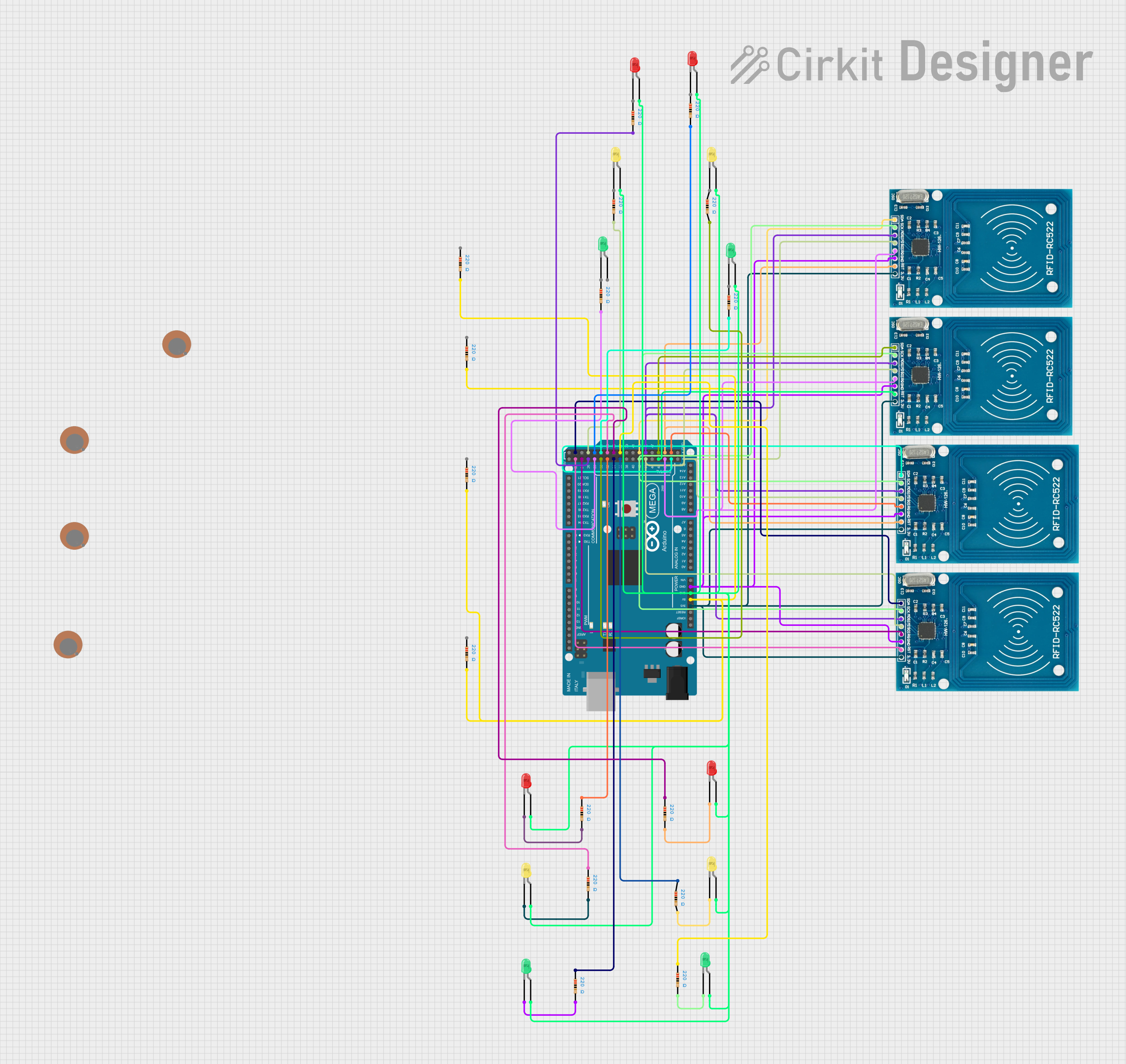
Arduino Mega 2560 RFID Interface with Status Indication LEDs

Circuit Documentation
Summary
This document provides a detailed overview of a circuit designed to interface multiple RFID-RC522 modules with an Arduino Mega 2560 microcontroller. The circuit includes a series of LEDs in different colors (red, green, and yellow), each paired with a resistor to limit the current. The RFID modules are powered by the 3.3V output from the Arduino, while the LEDs are powered by the 5V output. The circuit is designed to read RFID tags and provide visual feedback through the LEDs.
Component List
Microcontroller
- Arduino Mega 2560: A microcontroller board based on the ATmega2560, with a wide range of digital and analog I/O pins.
RFID Modules
- RFID-RC522: RFID reader modules that operate at 13.56 MHz, with SPI interface for communication.
LEDs
- LED (red): A two-pin red light-emitting diode.
- LED (green): A two-pin green light-emitting diode.
- LED (yellow): A two-pin yellow light-emitting diode.
Resistors
- Resistor: A passive two-terminal electrical component with a resistance of 220 Ohms, used to limit the current through the LEDs.
Sensors
- Piezo Sensor: A device that can detect vibration, touch, or shock.
Wiring Details
Arduino Mega 2560
- 3V3: Connected to the VCC (3.3V) pins of all RFID-RC522 modules.
- 5V: Connected to one side of all resistors.
- GND: Common ground for the Arduino, RFID modules, and LEDs.
- Digital Pins: Various digital pins are used to interface with the RFID modules and to control the LEDs through resistors.
RFID-RC522 Modules
- VCC (3.3V): Powered by the 3V3 output from the Arduino Mega 2560.
- RST: Connected to different digital pins on the Arduino for reset control.
- GND: Connected to the common ground.
- IRQ: Some connected to digital pins on the Arduino for interrupt requests.
- MISO, MOSI, SCK, SDA: Connected to corresponding SPI pins on the Arduino for SPI communication.
LEDs
- Anode: Connected to the 5V output from the Arduino through a 220 Ohm resistor.
- Cathode: Connected to the common ground.
Resistors
- One side: Connected to the 5V output from the Arduino.
- Other side: Connected to the anode of the corresponding LED.
Documented Code
Arduino Mega 2560 - sketch.ino
void setup() {
  // put your setup code here, to run once:

}

void loop() {
  // put your main code here, to run repeatedly:

}
Arduino Mega 2560 - documentation.txt
(No additional documentation provided)
This concludes the documentation for the given circuit. The circuit is designed to be modular, allowing for easy expansion or modification. The provided code template serves as a starting point for further development of the RFID reading functionality and LED control logic.