
Arduino-Controlled LDR-Triggered Relay for AC LED Bulb Illumination
View and Edit Project In Cirkit Designer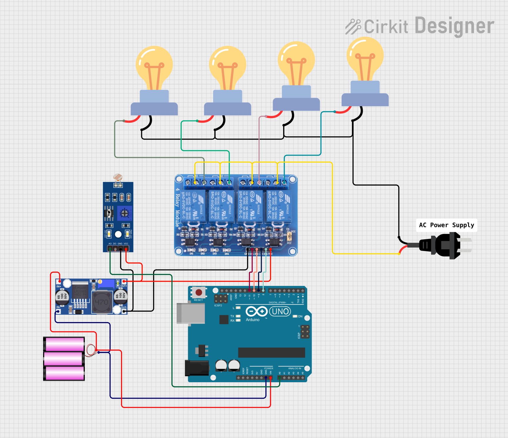
Circuit Documentation
Summary
This circuit is designed to control multiple AC-powered LED bulbs using an Arduino UNO microcontroller and a 4-channel relay module. The circuit is powered by a 12V battery, which is stepped down to a suitable voltage for the Arduino and other components using a buck converter. An LDR (Light Dependent Resistor) is included to provide input to the Arduino for potential light-based control logic. The AC power source is used to supply the LED bulbs, with the relay acting as an intermediary to control the power flow to each bulb.
Component List
LDR (Light Dependent Resistor)
- Pins: A0, D0, GND, VCC
- Description: A sensor that changes resistance based on light intensity.
Battery 12V
- Pins: +, -
- Description: Provides the primary power source for the circuit.
Buck Converter
- Pins: IN+, IN-, OUT+, OUT-
- Description: Steps down the voltage from the battery to a lower level suitable for the Arduino and other components.
LED Bulb AC (Bombillo AC)
- Pins: +, -
- Description: AC-powered light-emitting diode bulbs.
Arduino UNO
- Pins: UNUSED, IOREF, Reset, 3.3V, 5V, GND, Vin, A0-A5, SCL, SDA, AREF, D0-D13
- Description: A microcontroller board based on the ATmega328P, used for controlling the logic of the circuit.
Relay 4 Channel 5V
- Pins: GND, IN1-IN4, VCC, COM1-COM4, NO1-NO4, NC1-NC4
- Description: A module with 4 relays that can control high power devices such as the LED bulbs.
AC Source
- Pins: -, +
- Description: Provides alternating current to power the LED bulbs.
Wiring Details
LDR (Light Dependent Resistor)
- A0: Connected to Arduino A0 pin.
- GND: Connected to Buck Converter OUT-.
- VCC: Connected to Buck Converter OUT+.
Battery 12V
- + (Positive): Connected to Buck Converter IN+ and Arduino Vin.
- - (Negative): Connected to Buck Converter IN- and Arduino GND.
Buck Converter
- IN+: Connected to Battery 12V +.
- IN-: Connected to Battery 12V -.
- OUT+: Connected to LDR VCC and Relay VCC.
- OUT-: Connected to LDR GND and Relay GND.
LED Bulb AC (Bombillo AC)
- + (Positive): Each bulb's positive pin is connected to a corresponding NO (Normally Open) pin on the Relay module.
- - (Negative): All bulbs' negative pins are connected to the AC source +.
Arduino UNO
- GND: Connected to Battery 12V -.
- Vin: Connected to Battery 12V +.
- A0: Connected to LDR A0.
- D8-D11: Connected to Relay IN1-IN4 respectively.
Relay 4 Channel 5V
- GND: Connected to Buck Converter OUT-.
- IN1-IN4: Connected to Arduino D11-D8 respectively.
- VCC: Connected to Buck Converter OUT+.
- COM1-COM4: All connected to AC source -.
- NO1-NO4: Each connected to a corresponding LED bulb +.
AC Source
- - (Negative): Connected to all COM pins on the Relay module.
- + (Positive): Connected to all negative pins of the LED bulbs.
Documented Code
Arduino UNO Code (sketch.ino)
void setup() {
  // put your setup code here, to run once:

}

void loop() {
  // put your main code here, to run repeatedly:

}
Note: The provided code is a template and does not contain any functional logic. It needs to be populated with the specific control code for the LDR sensor and relay operation.
Additional Documentation (documentation.txt)
No additional documentation code was provided.