
Arduino UNO-Based Smart Lighting System with Motion Detection and Energy Monitoring
View and Edit Project In Cirkit Designer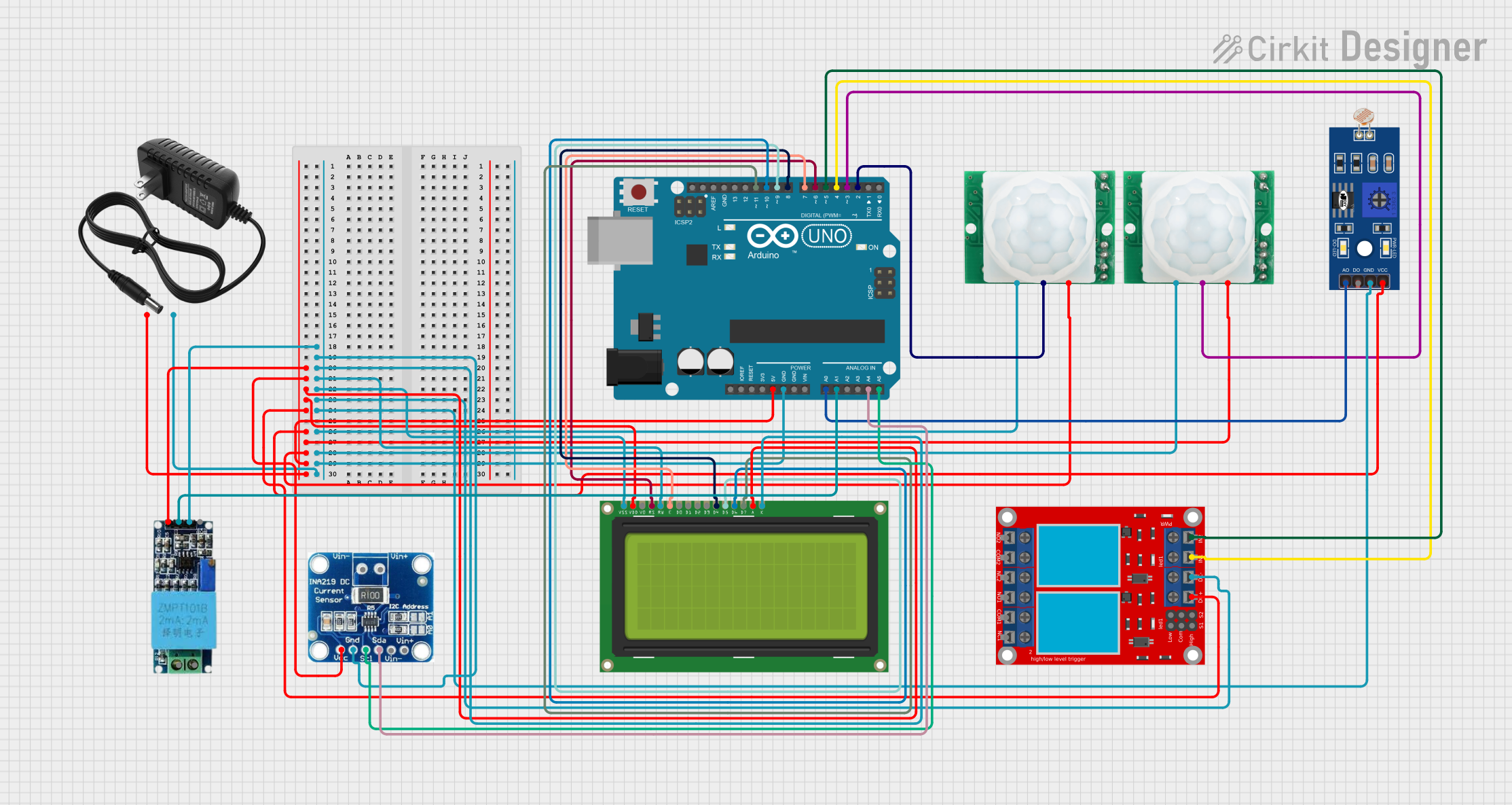
Circuit Documentation
Summary
This circuit is designed to monitor environmental parameters such as light intensity and motion, and control lighting based on these parameters. It uses an Arduino UNO as the central microcontroller to process sensor data and manage the connected devices. The circuit includes a light-dependent resistor (LDR) for light sensing, two HC-SR501 motion sensors for motion detection, a 2-channel relay module for controlling external loads, an LCD display for outputting sensor readings and system status, a current sensor, and a voltage sensor for monitoring electrical parameters. The system is also capable of interfacing with the Blynk platform for remote monitoring and control.
Component List
Arduino UNO: A microcontroller board based on the ATmega328P. It has digital input/output pins, analog inputs, and various power outputs.
12v Power Supply: Provides the necessary power to the circuit components.
HC-SR501 Motion Sensor: A PIR-based motion detector with digital output.
LDR (Light-Dependent Resistor): A sensor that changes resistance based on the ambient light level.
2-Channel Relay Module: An electrically operated switch that allows the Arduino to control higher power loads.
LCD Display 20x4: A 20 character by 4 line liquid crystal display for showing information.
Current Sensor: Measures the amount of current flowing through a conductor.
Voltage Sensor: Measures the voltage level of a conductor.
Wiring Details
Arduino UNO
- GND: Connected to the ground plane.
- 5V: Powers the VCC of the Voltage Sensor, Current Sensor, LCD Display, 2-Channel Relay Module, LDR, and both HC-SR501 Motion Sensors.
- A0: Connected to the LDR.
- A1: Connected to the Voltage Sensor output.
- A4: Connected to the SDA pin of the Current Sensor.
- A5: Connected to the SCL pin of the Current Sensor.
- D2: Connected to the OUT pin of one HC-SR501 Motion Sensor.
- D3: Connected to the OUT pin of the other HC-SR501 Motion Sensor.
- D4: Connected to the IN 1 pin of the 2-Channel Relay Module.
- D5: Connected to the IN 2 pin of the 2-Channel Relay Module.
- D6 - D11: Connected to the RS, E, DB4 - DB7 pins of the LCD Display respectively.
12v Power Supply
- +: Powers the VCC+ of the 2-Channel Relay Module.
- -: Connected to the ground plane.
HC-SR501 Motion Sensor
- GND: Connected to the ground plane.
- VCC: Powered by the 5V output from the Arduino UNO.
- OUT: Connected to the Arduino UNO digital pins D2 and D3.
LDR
- GND: Connected to the ground plane.
- VCC: Powered by the 5V output from the Arduino UNO.
- A0: Connected to the Arduino UNO analog pin A0.
2-Channel Relay Module
- VCC+: Powered by the 12v Power Supply.
- VCC- (GND): Connected to the ground plane.
- IN 1, IN 2: Controlled by the Arduino UNO digital pins D4 and D5.
LCD Display 20x4
- VSS, RW, LEDK: Connected to the ground plane.
- VDD, LEDA: Powered by the 5V output from the Arduino UNO.
- RS, E, DB4 - DB7: Controlled by the Arduino UNO digital pins D6 - D11.
Current Sensor
- gnd: Connected to the ground plane.
- Vcc: Powered by the 5V output from the Arduino UNO.
- Sda: Connected to the Arduino UNO analog pin A4.
- SCl: Connected to the Arduino UNO analog pin A5.
Voltage Sensor
- Ground: Connected to the ground plane.
- Vcc: Powered by the 5V output from the Arduino UNO.
- Out: Connected to the Arduino UNO analog pin A1.
Documented Code
#include <LiquidCrystal.h>
#include <BlynkSimpleEsp8266.h>

#define LDR_PIN A0
#define PIR1_PIN 2
#define PIR2_PIN 3
#define LIGHT_PIN1 4
#define LIGHT_PIN2 5
#define CURRENT_SENSOR_PIN A1
#define VOLTAGE_SENSOR_PIN A2

LiquidCrystal lcd(7, 8, 9, 10, 11, 12);
char auth[] = "YourBlynkAuthToken";
char ssid[] = "YourWiFiSSID";
char pass[] = "YourWiFiPassword";

bool lightOn = false;
unsigned long lastMotionTime = 0;
unsigned long lightOnTime = 0;
const int threshold = 500; // Adjust this threshold based on your LDR readings

void setup() {
  pinMode(LDR_PIN, INPUT);
  pinMode(PIR1_PIN, INPUT);
  pinMode(PIR2_PIN, INPUT);
  pinMode(LIGHT_PIN1, OUTPUT);
  pinMode(LIGHT_PIN2, OUTPUT);
  lcd.begin(16, 2);
  Blynk.begin(auth, ssid, pass);
  Serial.begin(9600);
}

void loop() {
  Blynk.run();
  int ldrValue = analogRead(LDR_PIN);
  int current = analogRead(CURRENT_SENSOR_PIN);
  int voltage = analogRead(VOLTAGE_SENSOR_PIN);

  lcd.setCursor(0, 0);
  lcd.print("V: ");
  lcd.print(voltage);
  lcd.print(" I: ");
  lcd.print(current);

  if (ldrValue < threshold) {
    if (!lightOn) {
      analogWrite(LIGHT_PIN1, 255); // 100% brightness
      analogWrite(LIGHT_PIN2, 255); // 100% brightness
      lightOn = true;
      lightOnTime = millis();
    }
  } else {
    if (lightOn) {
      analogWrite(LIGHT_PIN1, 0); // Turn off
      analogWrite(LIGHT_PIN2, 0); // Turn off
      lightOn = false;
    }
  }

  if (lightOn && millis() - lightOnTime > 300000) { // After 5 minutes
    analogWrite(LIGHT_PIN1, 128); // 50% brightness
    analogWrite(LIGHT_PIN2, 128); // 50% brightness
  }

  if (digitalRead(PIR1_PIN) == HIGH || digitalRead(PIR2_PIN) == HIGH) {
    analogWrite(LIGHT_PIN1, 255); // 100% brightness
    analogWrite(LIGHT_PIN2, 255); // 100% brightness
    lastMotionTime = millis();
  }

  if (millis() - lastMotionTime > 20000 && lightOn && millis() - lightOnTime > 300000) { // After 20 seconds and 5 minutes
    analogWrite(LIGHT_PIN1, 128); // 50% brightness
    analogWrite(LIGHT_PIN2, 128); // 50% brightness
  }

  Blynk.virtualWrite(V1, voltage);
  Blynk.virtualWrite(V2, current);
}

BLYNK_WRITE(V0) {
  int pinValue = param.asInt();
  if (pinValue == 1) {
    analogWrite(LIGHT_PIN1, 255); // 100% brightness
    analogWrite(LIGHT_PIN2, 255); // 100% brightness
  } else {
    analogWrite(LIGHT_PIN1, 0); // Turn off
    analogWrite(LIGHT_PIN2, 0); // Turn off
  }
}
This code is designed to run on the Arduino UNO microcontroller. It initializes the connected sensors and LCD display, then enters a loop where it reads sensor values, updates the display, and controls the relay module based on the sensor inputs. It also includes Blynk library calls for remote monitoring and control.