ESP32-Based Multi-Sensor Monitoring System
Circuit Documentation
Summary
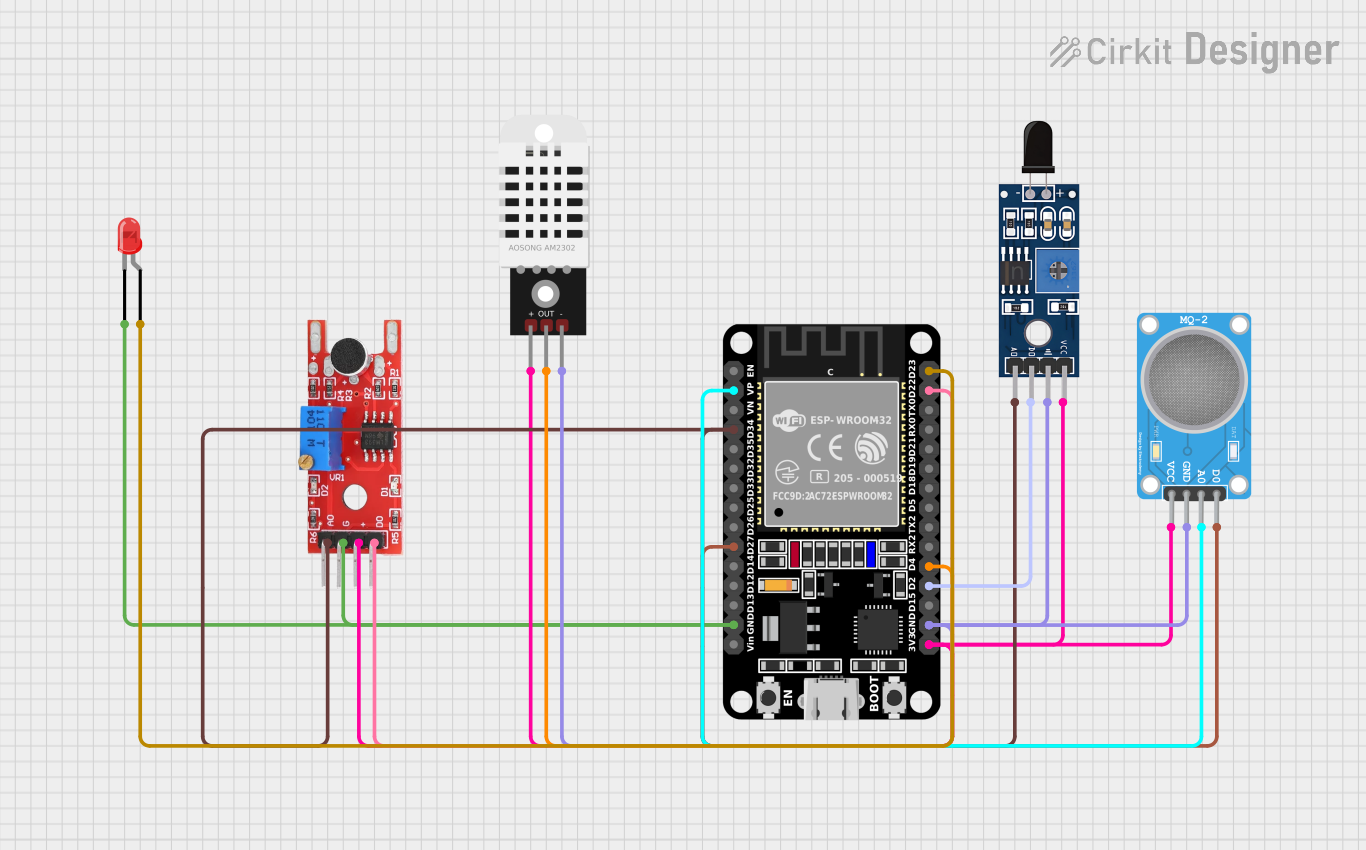
The circuit in question is designed to interface an ESP32 microcontroller with a variety of sensors and an LED. The sensors include the KY-038 sound sensor, MQ-2 gas sensor, DHT22 temperature and humidity sensor, and the SHT113 flame sensor. The circuit is designed to monitor environmental parameters such as sound, gas concentration, temperature, humidity, and flame presence. The ESP32 serves as the central processing unit, reading sensor data and controlling an LED indicator.
Component List
ESP32 (30 pin)
- Description: A microcontroller with Wi-Fi and Bluetooth capabilities, featuring a wide range of GPIO pins for interfacing with various sensors and peripherals.
- Pins: EN, VP, VN, D34, D35, D32, D33, D25, D26, D27, D14, D12, D13, GND, Vin, D23, D22, TX0, RX0, D21, D19, D18, D5, TX2, RX2, D4, D2, D15, 3V3
KY-038 Sound Sensor
- Description: A sound detection sensor module that features both analog and digital outputs.
- Pins: +, G, A0, D0
MQ-2 Gas Sensor
- Description: A sensor for detecting LPG, propane, hydrogen, and other combustible gases.
- Pins: VCC, GND, A0, D0
DHT22 Temperature and Humidity Sensor
- Description: A sensor for measuring ambient temperature and humidity.
- Pins: +, Out, -
SHT113 Flame Sensor
- Description: A sensor designed to detect the presence of a flame or fire.
- Pins: A0, D0, GND, VCC
LED: Two Pin (red)
- Description: A basic red LED for indication purposes.
- Pins: cathode, anode
Wiring Details
ESP32 (30 pin)
- VP connected to MQ-2 SENSOR A0
- D34 connected to Sensor SHT113 Flame A0 and KY 038 A0
- D27 connected to MQ-2 SENSOR D0
- GND connected to LED: Two Pin (red) cathode, KY 038 G, DHT22 -, Sensor SHT113 Flame GND, MQ-2 SENSOR GND
- D23 connected to LED: Two Pin (red) anode
- D22 connected to KY 038 D0
- D4 connected to DHT22 Out
- D2 connected to Sensor SHT113 Flame D0
- 3V3 connected to DHT22 +, Sensor SHT113 Flame VCC, MQ-2 SENSOR VCC, KY 038 +
KY-038 Sound Sensor
- connected to ESP32 3V3
- G connected to ESP32 GND
- A0 connected to ESP32 D34
- D0 connected to ESP32 D22
MQ-2 Gas Sensor
- VCC connected to ESP32 3V3
- GND connected to ESP32 GND
- A0 connected to ESP32 VP
- D0 connected to ESP32 D27
DHT22 Temperature and Humidity Sensor
- connected to ESP32 3V3
- Out connected to ESP32 D4
- connected to ESP32 GND
SHT113 Flame Sensor
- A0 connected to ESP32 D34
- D0 connected to ESP32 D2
- GND connected to ESP32 GND
- VCC connected to ESP32 3V3
LED: Two Pin (red)
- cathode connected to ESP32 GND
- anode connected to ESP32 D23
Documented Code
No code has been provided for the microcontroller. The documentation of the code would typically include a description of the functionality, setup, and loop routines, along with any functions or libraries used to interface with the sensors and control the LED. Since no code is available, this section cannot be completed.