
ESP32 and MQ-2 Gas Sensor with Wi-Fi Notification and Battery Power
View and Edit Project In Cirkit Designer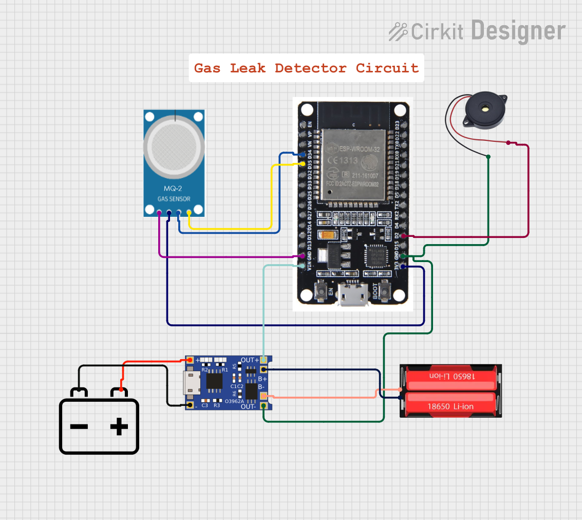
Circuit Documentation
Summary
This circuit is designed to detect gas leakage using an MQ-2 gas sensor and an ESP32 microcontroller. When gas is detected above a certain threshold, a buzzer is activated, and a notification is sent via the Blynk platform. The circuit is powered by a 12V battery and includes a TP4056 module for charging a 18650 Li-Ion battery.
Component List
MQ-2 Gas Sensor
- Description: Gas sensor for detecting LPG, i-butane, propane, methane, alcohol, Hydrogen, and smoke.
- Pins: GND, VCC, ANALOG, Digital
ESP32 Microcontroller
- Description: A low-power system on a chip microcontroller with integrated Wi-Fi and dual-mode Bluetooth.
- Pins: EN, VP, VN, D34, D35, D32, D33, D25, D26, D27, D14, D12, D13, GND, VIN, 3V3, D15, D2, D4, RX2, TX2, D5, D18, D19, D21, RX0, TX0, D22, D23, BOOT
Buzzer
- Description: An audio signaling device.
- Pins: GND, IN
18650 Li-Ion Battery
- Description: Rechargeable lithium-ion battery.
- Pins: Positive, Negative
TP4056 Charging Module
- Description: Lithium battery charger module with overcharge protection.
- Pins: OUT-, B-, B+, OUT+, IN-, IN+
12V Battery
- Description: Power source for the circuit.
- Pins: -, +
Wiring Details
MQ-2 Gas Sensor
- GND connected to ESP32 GND
- VCC connected to ESP32 3V3
- ANALOG connected to ESP32 D34
- Digital connected to ESP32 D35
ESP32 Microcontroller
- VIN connected to TP4056 OUT+
- GND connected to MQ-2 GND, Buzzer GND, TP4056 OUT-
- D2 connected to Buzzer IN
Buzzer
- GND connected to ESP32 GND
- IN connected to ESP32 D2
18650 Li-Ion Battery
- Positive connected to TP4056 B+
- Negative connected to TP4056 B-
TP4056 Charging Module
- OUT+ connected to ESP32 VIN
- OUT- connected to ESP32 GND
- B+ connected to 18650 Li-Ion Battery Positive
- B- connected to 18650 Li-Ion Battery Negative
- IN- connected to 12V Battery -
- IN+ connected to 12V Battery +
12V Battery
- - connected to TP4056 IN-
- + connected to TP4056 IN+
Code Documentation
#define BLYNK_TEMPLATE_ID "YourTemplateID"
#define BLYNK_DEVICE_NAME "YourDeviceName"
#define BLYNK_AUTH_TOKEN "YourAuthToken"

#include <WiFi.h>
#include <BlynkSimpleEsp32.h>

char auth[] = BLYNK_AUTH_TOKEN;
char ssid[] = "YourSSID";
char pass[] = "YourPassword";

const int gasSensorPin = 34; // Analog pin connected to MQ-2 A0
const int buzzerPin = 25;    // Digital pin connected to Buzzer Signal
const int threshold = 300;   // Threshold value for gas detection

void setup() {
  Serial.begin(115200);
  Blynk.begin(auth, ssid, pass);
  pinMode(gasSensorPin, INPUT);
  pinMode(buzzerPin, OUTPUT);
}

void loop() {
  Blynk.run();
  int gasLevel = analogRead(gasSensorPin);
  Serial.print("Gas Level: ");
  Serial.println(gasLevel);

  if (gasLevel > threshold) {
    digitalWrite(buzzerPin, HIGH);
    Blynk.notify("Gas Leakage Detected!");
  } else {
    digitalWrite(buzzerPin, LOW);
  }
}
This code initializes the ESP32 microcontroller, connects it to a Wi-Fi network, and sets up the Blynk platform for remote notifications. The gas sensor's analog output is read, and if the gas level exceeds a predefined threshold, the buzzer is activated, and a notification is sent via Blynk.