Cirkit Designer
Your all-in-one circuit design IDE
Home /
Project Documentation
Arduino-Controlled IR Remote Solenoid Activation System
Circuit Documentation
Summary
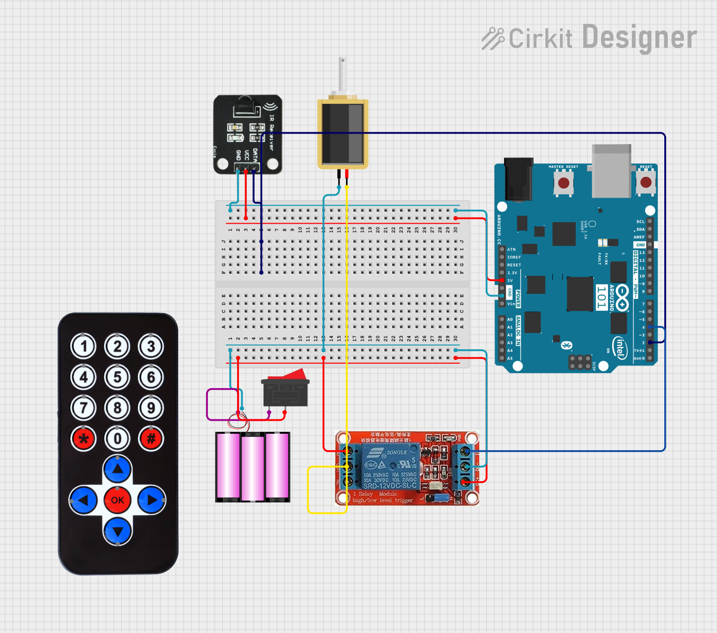
This circuit is designed to activate a solenoid using an IR remote control. When the '1' button on the remote is pressed, the Arduino 101 microcontroller activates a relay, which in turn powers the solenoid. The circuit includes an IR receiver to capture signals from the remote, a 12V battery to power the solenoid and relay, and a rocker switch to control the power supply.
Component List
Solenoid
- Description: Electromechanical device that converts electrical energy into mechanical motion.
- Pins: pin1, pin2
Arduino 101
- Description: Microcontroller board based on the Intel Curie module.
- Pins: A5/SCL, A4/SDA, AREF, GND, D13/SCK, D12/MISO, D11 PWM/MOSI, D10 PWM/SS, D9 PWM, D8, D7, D6 PWM, D5 PWM, D4, D3 PWM, D2, D1/TX, D0/RX, AIN, ioref, RESET, 3V3, 5V, VIN, A0, A1, A2, A3, ICSP MISO, ICSP SCK, ICSP MOSI
Rocker Switch
- Description: A switch that rocks back and forth to open or close a circuit.
- Pins: 1, 2
Battery 12V
- Description: Power source providing 12V DC.
- Pins: +, -
HX1838 Infrared IR Wireless Remote Control
- Description: Remote control for sending IR signals.
- Pins: FFA25D (1), FF629D (2), FFE21D (3), FF22DD (4), FF02FD (5), FFC23D (6), FFE01F (7), FFA857 (8), FF906F (9), FF9867 (0), FFB04F (#), FF6897 (*), FF18E7 (↑), FF5AA5 (→), FF10EF (←), FF4AB5 (↓), FF38C7 (OK)
IR Receiver
- Description: Device that receives IR signals from the remote control.
- Pins: DATA, VCC, GND
12V Relay
- Description: Electromechanical switch that uses a 12V signal to control a higher power circuit.
- Pins: NO, COM, NC, IN, DC-, DC+
Wiring Details
Solenoid
- pin1 connected to battery 12V (-)
- pin2 connected to 12V Relay (COM)
Arduino 101
- D2 connected to IR Receiver (DATA)
- GND connected to IR Receiver (GND)
- 5V connected to IR Receiver (VCC)
- D4 connected to 12V Relay (IN)
Rocker Switch
- Pin 1 connected to battery 12V (+)
- Pin 2 connected to 12V Relay (NO) and 12V Relay (DC+)
Battery 12V
- + connected to Rocker Switch (Pin 1)
- - connected to Solenoid (pin1) and 12V Relay (DC-)
IR Receiver
- DATA connected to Arduino 101 (D2)
- VCC connected to Arduino 101 (5V)
- GND connected to Arduino 101 (GND)
12V Relay
- NO connected to Rocker Switch (Pin 2)
- COM connected to Solenoid (pin2)
- IN connected to Arduino 101 (D4)
- DC- connected to battery 12V (-)
- DC+ connected to Rocker Switch (Pin 2)
Code Documentation
Arduino 101 Code
/*
 * This Arduino sketch is designed to activate a relay when the '1' button on
 * an IR remote control is pressed. The relay, in turn, activates a solenoid.
 */

#include <IRremote.h>

const int RECV_PIN = 2; // Pin connected to IR receiver DATA pin
const int RELAY_PIN = 4; // Pin connected to relay IN pin

IRrecv irrecv(RECV_PIN);
decode_results results;

void setup() {
  pinMode(RELAY_PIN, OUTPUT);
  irrecv.enableIRIn(); // Start the IR receiver
}

void loop() {
  if (irrecv.decode(&results)) {
    if (results.value == 0xFFA25D) { // '1' button on the remote
      digitalWrite(RELAY_PIN, HIGH); // Activate relay
      delay(1000); // Keep relay on for 1 second
      digitalWrite(RELAY_PIN, LOW); // Deactivate relay
    }
    irrecv.resume(); // Receive the next value
  }
}
12V Relay Code
void setup() {
  // put your setup code here, to run once:
}

void loop() {
  // put your main code here, to run repeatedly:
}
This documentation provides a comprehensive overview of the circuit, including a summary, detailed component list, wiring details, and the code used in the microcontrollers.