
Arduino-Controlled Flame Detection and Motion-Activated Water Pump System
View and Edit Project In Cirkit Designer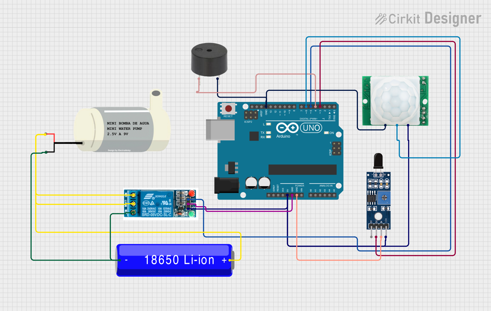
Circuit Documentation
Summary
The circuit in question is designed to interface a variety of sensors and actuators with an Arduino UNO microcontroller. The circuit includes a flame sensor, a motion sensor, a relay module, a mini water pump, a buzzer, and a power source in the form of an 18650 Li-ion battery. The Arduino UNO is used to process signals from the sensors and control the relay, which in turn controls the mini water pump. The buzzer provides an audible alert, and the entire circuit is powered by the 5V output from the Arduino as well as the battery for the pump.
Component List
Sensor SHT113 Flame
- A flame detection sensor that outputs a digital signal.
- Pins: A0, D0, GND, VCC
5v Relay
- An electromechanical switch that allows the Arduino to control higher power devices like the mini water pump.
- Pins: Normally Open, Common terminal, Normally Closed, In, GND, VCC
Arduino UNO
- A microcontroller board based on the ATmega328P, used for processing sensor data and controlling other components.
- Pins: UNUSED, IOREF, Reset, 3.3V, 5V, GND, Vin, A0-A5, SCL, SDA, AREF, D0-D13
Mini Water Pump
- A small pump used for moving water, controlled by the relay.
- Pins: VCC, GND
Buzzer
- An audible signaling device.
- Pins: PIN, GND
HC-SR501 Motion Sensor
- A passive infrared sensor that detects motion.
- Pins: GND, OUT, VCC
18650 Li-ion Battery
- A rechargeable battery that provides power to the mini water pump through the relay.
- Pins: -, +
Wiring Details
Sensor SHT113 Flame
- D0 connected to Arduino UNO D3
- GND connected to Arduino UNO GND
- VCC connected to Arduino UNO 5V
5v Relay
- Normally Open connected to Mini Water Pump VCC
- Common terminal connected to 18650 Li-ion Battery +
- Normally Closed not used in this circuit
- In connected to Arduino UNO D5
- GND connected to Arduino UNO GND
- VCC connected to Arduino UNO 5V
Arduino UNO
- D3 connected to Sensor SHT113 Flame D0
- D4 connected to Buzzer PIN
- D5 connected to 5v Relay In
- D6 connected to HC-SR501 Motion Sensor OUT
- 5V connected to Sensor SHT113 Flame VCC, HC-SR501 Motion Sensor VCC, and 5v Relay VCC
- GND connected to Sensor SHT113 Flame GND, 5v Relay GND, HC-SR501 Motion Sensor GND, and Buzzer GND
Mini Water Pump
- VCC connected to 18650 Li-ion Battery + through 5v Relay Normally Open
- GND connected to 18650 Li-ion Battery -
Buzzer
- PIN connected to Arduino UNO D4
- GND connected to Arduino UNO GND
HC-SR501 Motion Sensor
- OUT connected to Arduino UNO D6
- GND connected to Arduino UNO GND
- VCC connected to Arduino UNO 5V
18650 Li-ion Battery
-
- connected to Mini Water Pump VCC through 5v Relay Common terminal
-
- connected to Mini Water Pump GND
Documented Code
void setup() {
  // put your setup code here, to run once:

}

void loop() {
  // put your main code here, to run repeatedly:

}
The provided code is a template for the Arduino UNO microcontroller. The setup() function is called once when the microcontroller is powered on or reset. It is used to initialize the pins and set the initial state of the circuit. The loop() function is called repeatedly and contains the main logic of the program. It will check the sensors and control the actuators based on the sensor inputs.
The actual implementation details are not provided in the code snippet. To complete the circuit functionality, the user would need to add code to read the sensors, process the input, and control the relay, buzzer, and other components accordingly.