
Arduino Nano-Based Motion-Activated Alarm with PIR Sensor and Buzzer
View and Edit Project In Cirkit Designer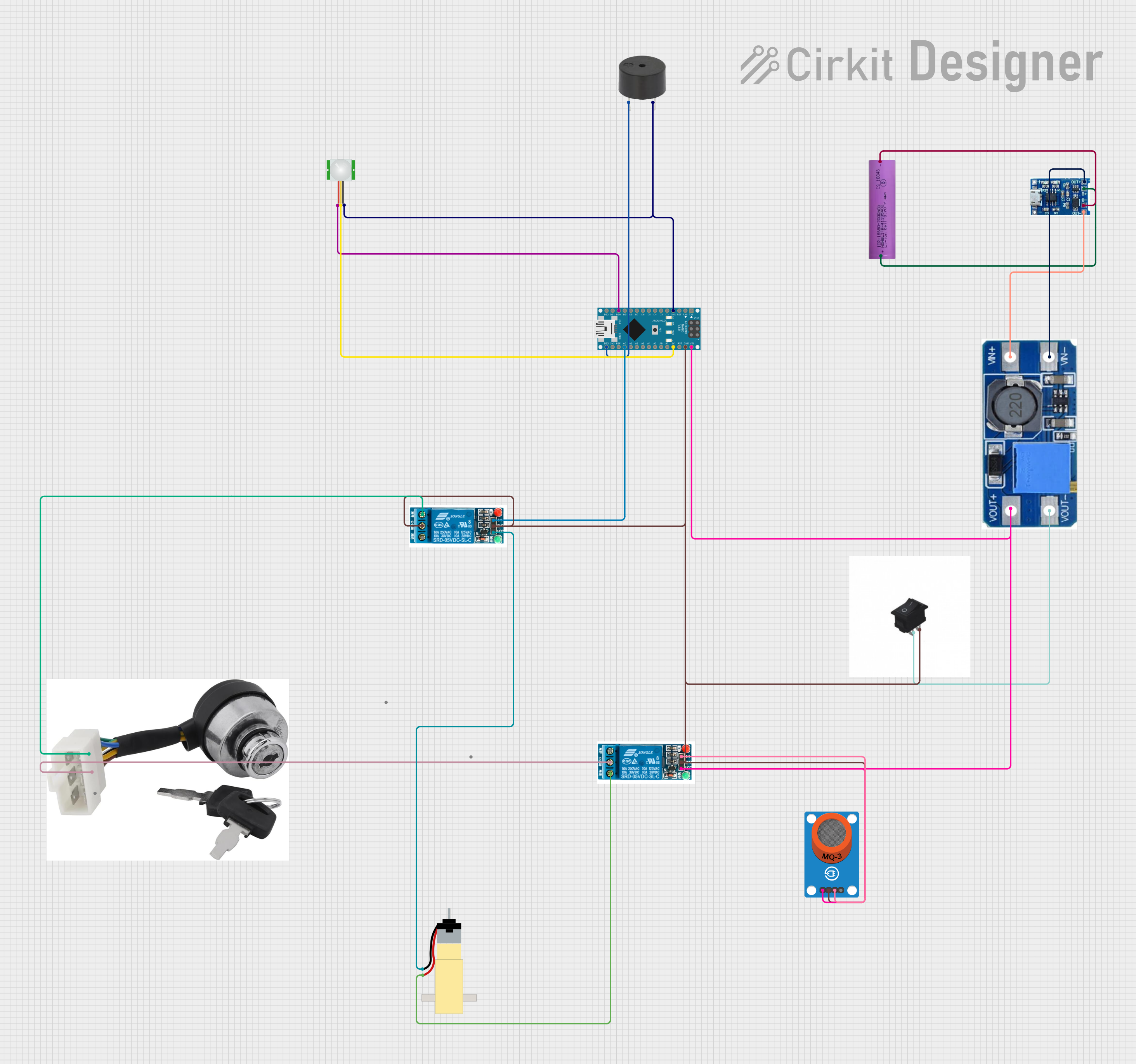
Circuit Documentation
Summary
This circuit is designed to interface an Arduino Nano with a variety of components including a buzzer, PIR sensor, Li-ion battery, power converter, battery charger module, rocker switch, relays, MQ-3 gas sensor, ignition switch, and a hobby gearmotor. The Arduino Nano acts as the central processing unit, controlling the relay and buzzer based on input from the PIR sensor and the MQ-3 gas sensor. The circuit is powered by a Li-ion battery, which is managed by a charger module and a step-up boost power converter to ensure the correct voltage is supplied to the components. A rocker switch is used to control the power flow in the circuit.
Component List
- Arduino Nano: A compact microcontroller board based on the ATmega328P, featuring digital and analog I/O pins.
- Buzzer: An electromechanical component that emits sound when an electrical signal is applied.
- PIR Sensor: A passive infrared sensor used to detect motion by measuring changes in the infrared levels emitted by surrounding objects.
- Li-ion Battery (18650-2000mAh 3.7V 7.4WH): A rechargeable battery that provides power to the circuit.
- Step Up Boost Power Converter (Adjustable Voltage Regulator): A device that steps up the input voltage to a higher, regulated output voltage.
- Lipo Battery Charger Module: A module used to charge the Li-ion battery safely.
- Rocker Switch: A switch that allows the user to control the power supply to the circuit.
- 5V Relay: An electromechanical switch that allows a low-power signal to control a higher power circuit.
- MQ-3 Breakout: A gas sensor module used for detecting alcohol vapors.
- Ignition Switch: A switch that can be used to control power or trigger actions in the circuit.
- Hobby Gearmotor (48:1 Gearbox): A motor with a gearbox used for driving mechanical parts.
Wiring Details
Arduino Nano
- GND: Connected to the ground pins of the buzzer, PIR sensor, and the ground net of the circuit.
- D10: Connected to the VDD pin of the PIR sensor.
- VIN: Connected to the VOUT+ of the Step Up Boost Power Converter.
- 5V: Connected to the SIG pin of the PIR sensor.
- A0: Connected to the In pin of one of the 5V relays.
- D13/SCK: Connected to the PIN pin of the buzzer.
Buzzer
- PIN: Connected to D13/SCK on the Arduino Nano.
- GND: Connected to the ground net of the circuit.
PIR Sensor
- VDD: Connected to D10 on the Arduino Nano.
- SIG: Connected to 5V on the Arduino Nano.
- GND: Connected to the ground net of the circuit.
Li-ion Battery (18650-2000mAh 3.7V 7.4WH)
- +: Connected to the B+ pin of the Lipo Battery Charger Module.
- -: Connected to the B- pin of the Lipo Battery Charger Module.
Step Up Boost Power Converter (Adjustable Voltage Regulator)
- VOUT+: Connected to VIN on the Arduino Nano and VCC of the MQ-3 Breakout and one of the 5V relays.
- VOUT-: Connected to the rocker switch.
- VIN+: Connected to the OUT- of the Lipo Battery Charger Module.
- VIN-: Connected to the OUT+ of the Lipo Battery Charger Module.
Lipo Battery Charger Module
- B+: Connected to the + pin of the Li-ion Battery.
- B-: Connected to the - pin of the Li-ion Battery.
- OUT-: Connected to VIN+ on the Step Up Boost Power Converter.
- OUT+: Connected to VIN- on the Step Up Boost Power Converter.
Rocker Switch
- 1: Connected to the ground net of the circuit.
- 2: Connected to VOUT- on the Step Up Boost Power Converter.
5V Relay
- Normally Open: Connected to the vcc pin of the ignition switch.
- Common Terminal: Connected to the ground net of the circuit and the gnd pin of the ignition switch.
- Normally Closed: Connected to pin 2 of the Hobby Gearmotor.
- In: Connected to A0 on the Arduino Nano and DO on the MQ-3 Breakout.
- GND: Connected to the ground net of the circuit.
- VCC: Connected to VOUT+ on the Step Up Boost Power Converter.
MQ-3 Breakout
- VCC: Connected to VOUT+ on the Step Up Boost Power Converter.
- GND: Connected to the ground net of the circuit.
- DO: Connected to the In pin of one of the 5V relays.
Ignition Switch
- vcc: Connected to the Normally Open pin of one of the 5V relays.
- gnd: Connected to the Common Terminal pin of the other 5V relay.
Hobby Gearmotor (48:1 Gearbox)
- pin 1: Connected to the VCC pin of one of the 5V relays.
- pin 2: Connected to the Normally Closed pin of the other 5V relay.
Documented Code
#define Relay 13
#define buzzer A0
static const int sensorPin = 10;                    // sensor input pin
int SensorStatePrevious = LOW;                      // previous state of the sensor

unsigned long minSensorDuration = 3000; // Time we wait before the sensor active as long
unsigned long minSensorDuration2 = 6000;
unsigned long SensorLongMillis;                // Time in ms when the sensor was active
bool SensorStateLongTime = false;                  // True if it is a long active

const int intervalSensor = 50;                      // Time between two readings sensor state
unsigned long previousSensorMillis;                 // Timestamp of the latest reading

unsigned long SensorOutDuration;                  // Time the sensor is active in ms

//// GENERAL ////

unsigned long currentMillis;          // Variable to store the number of milliseconds since the Arduino has started

void setup() {
  Serial.begin(9600);                 // Initialise the serial monitor

  pinMode(sensorPin, INPUT);          // set sensorPin as input
  Serial.println("Press button");
  pinMode(Relay,OUTPUT);
  pinMode(buzzer,OUTPUT);
}

// Function for reading the sensor state
void readSensorState() {

  // If the difference in time between the previous reading is larger than intervalSensor
  if(currentMillis - previousSensorMillis > intervalSensor) {

    // Read the digital value of the sensor (LOW/HIGH)
    int SensorState = digitalRead(sensorPin);

    // If the button has been active AND
    // If the sensor wasn't activated before AND
    // IF there was not already a measurement running to determine how long the sensor has been activated
    if (SensorState == LOW && SensorStatePrevious == HIGH && !SensorStateLongTime) {
     SensorLongMillis = currentMillis;
       SensorStatePrevious = LOW;

      Serial.println("Button pressed");
    }

    // Calculate how long the sensor has been activated
   SensorOutDuration = currentMillis - SensorLongMillis;

    // If the button is active AND
    // If there is no measurement running to determine how long the sensor is active AND
    // If the time the sensor has been activated is larger or equal to the time needed for a long active
    if (SensorState == LOW && !SensorStateLongTime && SensorOutDuration >= minSensorDuration) {
      SensorStateLongTime = true;
      digitalWrite(Relay,HIGH);
      Serial.println("Button long pressed");
    }
    if (SensorState == LOW && SensorStateLongTime && SensorOutDuration >= minSensorDuration2) {
     SensorStateLongTime = true;
      digitalWrite(buzzer,HIGH);
      delay(1000);
      Serial.println("Button long pressed");
    }

    // If the sensor is released AND
    // If the sensor was activated before
    if (SensorState == HIGH && SensorStatePrevious == LOW) {
      SensorStatePrevious = HIGH;
      SensorStateLongTime = false;
      digitalWrite(Relay,LOW);
      digitalWrite(buzzer,LOW);
      Serial.println("Button released");

    }

    // store the current timestamp in previousSensorMillis
   previousSensorMillis = currentMillis;

  }

}

void loop() {

  currentMillis = millis();    // store the current time
  readSensorState();           // read the sensor state

}
This code is designed to run on the Arduino Nano and controls a relay and a buzzer based on the input from a PIR sensor. The code defines the pin connections, sets up the serial communication, and initializes the pins. It includes a function readSensorState() that checks the state of the PIR sensor and activates the relay and buzzer accordingly. The loop() function continuously updates the current time and calls readSensorState() to process the sensor input.