
Circuit Documentation
Summary
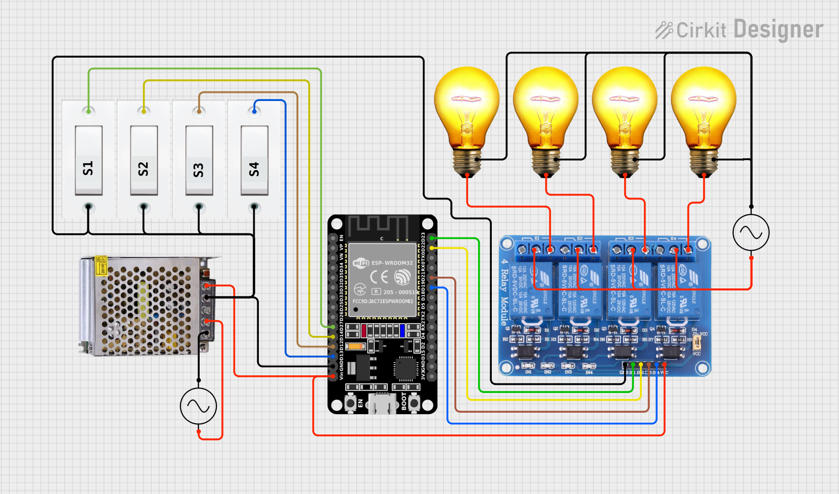
This circuit is designed to control multiple AC bulbs using an ESP32 microcontroller and a 4-channel relay module. The ESP32 receives input from flush switches and controls the relay channels accordingly, which in turn switch the AC bulbs on or off. The power supply unit converts AC voltage to 5V DC to power the ESP32 and the relay module.
Component List
Microcontroller
- ESP32 (30 pin): A microcontroller with WiFi and Bluetooth capabilities, featuring a variety of digital input/output pins.
Relay Module
- Relay 4 Channel 5v: A module with four relays capable of controlling high power devices such as AC bulbs. Each relay has a Normally Open (NO) and a Common (COM) terminal.
Power Supply
- POWER SUPPLY 5V 5AMP: Converts 220V AC to 5V DC to power the ESP32 and the relay module.
AC Supply
- Ac Supply: Provides the 220V AC source for the circuit.
AC Bulbs
- AC Bulb: Standard AC bulbs that are controlled by the relay module.
Flush Switches
- Flush Switch: A simple push-button switch used to provide input to the ESP32.
Comments
- Comment: Used for annotations or notes within the circuit design, not a physical component.
Wiring Details
ESP32 (30 pin)
EN,VP,VN,D34,D35,D32,D33,D25,D26,TX0,RX0,D18,D5,TX2,RX2,D4,D2,D15,3V3: Not connected.D27,D14,D12,D13: Connected to the VCC of different Flush Switches.GND: Common ground with POWER SUPPLY, Relay Module, and all Flush Switches.Vin: Connected to the 12V-24V Output (DC) of the POWER SUPPLY 5V 5AMP.D23,D22,D21,D19: Connected to the IN1, IN2, IN3, IN4 of the Relay 4 Channel 5v respectively.
Relay 4 Channel 5v
GND: Common ground with ESP32 and Flush Switches.IN1,IN2,IN3,IN4: Controlled by ESP32 pins D23, D22, D21, D19 respectively.VCC: Powered by the 12V-24V Output (DC) of the POWER SUPPLY 5V 5AMP.COM1,COM2,COM3,COM4: Connected to the -ve of the Ac Supply.NO1,NO2,NO3,NO4: Connected to the P terminal of different AC Bulbs.
POWER SUPPLY 5V 5AMP
220V Positive Pole (AC),220V Negative Pole (AC): Connected to the Ac Supply.GND (DC): Common ground with ESP32 and Flush Switches.12V-24V Output (DC): Powers the ESP32 and the Relay Module.
Ac Supply
+ve,-ve: Provides 220V AC to the POWER SUPPLY 5V 5AMP and the Relay Module.
AC Bulbs
P: Connected to the NO terminals of the Relay Module.N: Common connection with the +ve of the Ac Supply.
Flush Switches
GND: Common ground with ESP32, Relay Module, and POWER SUPPLY.VCC: Connected to different GPIO pins on the ESP32 (D27, D14, D12, D13).
Documented Code
No code has been provided for the microcontrollers in the circuit. The ESP32 is expected to be programmed to read the state of the flush switches and control the relay channels accordingly, which would switch the AC bulbs on or off based on the input from the switches.
Please note that the actual implementation of the code would be necessary to complete the documentation, as it would provide details on the logic and functionality of the circuit.