
Arduino UNO Controlled Stepper Motor with Manual Morse Switch Interface
View and Edit Project In Cirkit Designer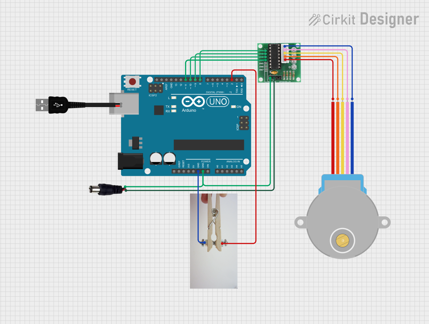
Circuit Documentation
Summary
This circuit is designed to control a 28BYJ-48 Stepper Motor using an Arduino UNO as the microcontroller and a ULN2003 driver board. The Arduino UNO interfaces with the ULN2003 to drive the stepper motor in response to inputs from a Morse Switch. The power jack provides the necessary power to the circuit, and the USB male 2-pin connection is likely used for power or data transfer.
Component List
Arduino UNO
- Microcontroller board based on the ATmega328P.
- It has 14 digital input/output pins, 6 analog inputs, a 16 MHz quartz crystal, a USB connection, a power jack, an ICSP header, and a reset button.
28BYJ-48 Stepper Motor
- A small, 5V geared stepping motor with a 1/64 reduction gear ratio.
- It has 5 wires for connecting to the driver board.
ULN2003
- A 7-channel Darlington array which is used to interface between low-level logic signals and higher-power loads.
- This IC is commonly used to drive relays, lamps, and stepper motors.
Power Jack
- A connector for supplying power to the circuit.
- It typically has a positive and a negative terminal.
USB Male 2 Pin Connection
- A USB connector that can be used for power supply or data transfer.
- It has two pins: positive and negative.
Morse Switch
- A switch that can be used to input Morse code or as a simple on/off switch.
- It has two terminals: live and switch.
Wiring Details
Arduino UNO
- GND connected to the GND of the power jack and the GND of the ULN2003.
- D11 connected to IN4 of the ULN2003.
- D10 connected to IN3 of the ULN2003.
- D9 connected to IN2 of the ULN2003.
- D8 connected to IN1 of the ULN2003.
- D2 connected to the Live terminal of the Morse Switch.
28BYJ-48 Stepper Motor
- BLUE connected to COIL1 of the ULN2003.
- PINK connected to COIL2 of the ULN2003.
- YELLOW connected to COIL3 of the ULN2003.
- ORANGE connected to COIL4 of the ULN2003.
- RED connected to COIL5 of the ULN2003.
ULN2003
- IN1 - IN4 connected to D8 - D11 of the Arduino UNO respectively.
- GND connected to the GND of the Arduino UNO.
- + connected to the POSITIF terminal of the power jack.
- COIL1 - COIL4 connected to the corresponding wires of the 28BYJ-48 Stepper Motor.
Power Jack
- NEGATIF connected to the GND of the Arduino UNO and the GND of the ULN2003.
- POSITIF connected to the + of the ULN2003.
Morse Switch
- Live connected to D2 of the Arduino UNO.
- Switch connected to GND of the Arduino UNO.
Documented Code
Arduino UNO Code (sketch.ino)
void setup() {
  // put your setup code here, to run once:

}

void loop() {
  // put your main code here, to run repeatedly:

}
Note: The provided code is a template and does not contain any functionality. It needs to be filled in with the logic to control the stepper motor and read inputs from the Morse Switch.