
Arduino-Controlled Water Management System with Solenoid Valves and Sensors
View and Edit Project In Cirkit Designer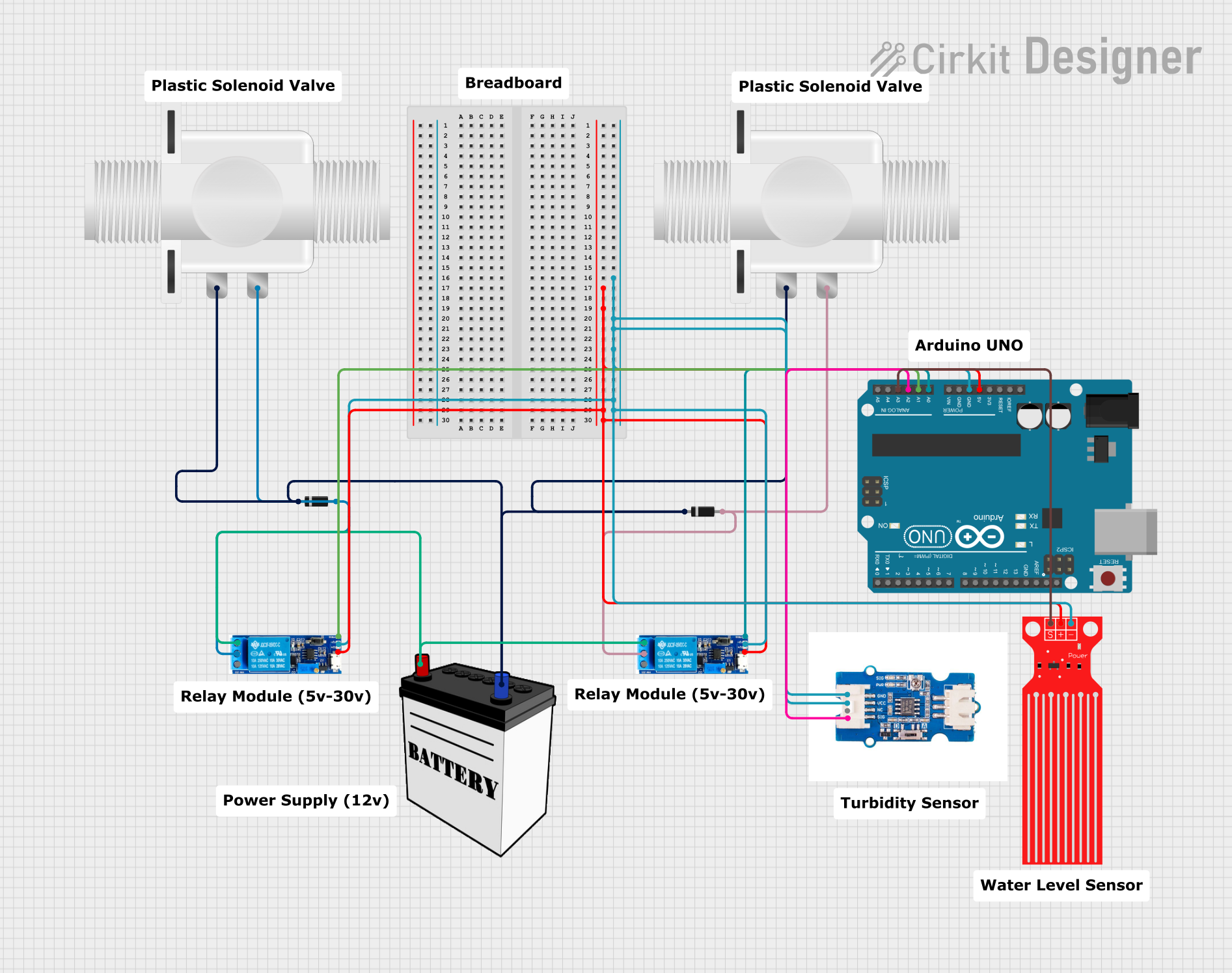
Circuit Documentation
Summary
The circuit in question appears to be designed for sensing water levels and turbidity, with the capability to control solenoid valves based on the sensor readings. It uses an Arduino UNO as the central microcontroller to process sensor data and control relay modules, which in turn manage the power flow to the solenoid valves. Diodes are used for protecting the circuit from reverse current. A 12V battery provides the power source for the solenoid valves and the relay modules.
Component List
Relay Module 5V-30V
- Description: A relay module capable of switching higher voltages and currents using a low voltage signal.
- Pins: common contact, normally open, normally closed, trigger, V-, V+
Diode
- Description: A semiconductor device that allows current to flow in one direction only, used for preventing reverse current flow.
- Pins: cathode, anode
Plastic Solenoid Valve
- Description: An electrically-controlled valve used for controlling the flow of liquid.
- Pins: pin1, pin2
12V Battery
- Description: A power source for the circuit.
- Pins: VCC, GND
Turbidity Sensor
- Description: A sensor for measuring the turbidity (cloudiness) of water.
- Pins: GND, VCC, NC, SIG
Water Level Sensor
- Description: A sensor for detecting the water level.
- Pins: SIG, VCC, GND
Arduino UNO
- Description: A microcontroller board based on the ATmega328P, used for controlling the logic of the circuit.
- Pins: UNUSED, IOREF, Reset, 3.3V, 5V, GND, Vin, A0-A5, SCL, SDA, AREF, D0-D13
Wiring Details
Relay Module 5V-30V
- Common Contact: Connected to the Plastic Solenoid Valve pin2.
- Normally Open: Connected to the 12V Battery VCC.
- Normally Closed: Not connected.
- Trigger: Connected to Arduino UNO A0 or A1 depending on the instance.
- V-: Connected to the GND net, shared with Arduino UNO GND, Turbidity Sensor GND, and Water Level Sensor GND.
- V+: Connected to the 5V net, shared with Arduino UNO 5V, Turbidity Sensor VCC, and Water Level Sensor VCC.
Diode
- Cathode: Connected to the 12V Battery GND.
- Anode: Connected to the Plastic Solenoid Valve pin2.
Plastic Solenoid Valve
- Pin1: Connected to the 12V Battery GND through Diodes.
- Pin2: Connected to the Relay Module 5V-30V common contact.
12V Battery
- VCC: Connected to the Relay Module 5V-30V normally open.
- GND: Connected to the Plastic Solenoid Valve pin1 through Diodes.
Turbidity Sensor
- GND: Connected to the GND net.
- VCC: Connected to the 5V net.
- NC: Not connected.
- SIG: Connected to Arduino UNO A2.
Water Level Sensor
- SIG: Connected to Arduino UNO A3.
- VCC: Connected to the 5V net.
- GND: Connected to the GND net.
Arduino UNO
- GND: Connected to the GND net.
- 5V: Connected to the 5V net.
- A0: Connected to Relay Module 5V-30V trigger (instance specific).
- A1: Connected to Relay Module 5V-30V trigger (instance specific).
- A2: Connected to Turbidity Sensor SIG.
- A3: Connected to Water Level Sensor SIG.
Documented Code
Arduino UNO Code (sketch.ino)
void setup() {
  // put your setup code here, to run once:

}

void loop() {
  // put your main code here, to run repeatedly:

}
Note: The provided code is a template and does not contain any functional code. It needs to be populated with the logic for reading sensors and controlling the relay modules based on the sensor data.