
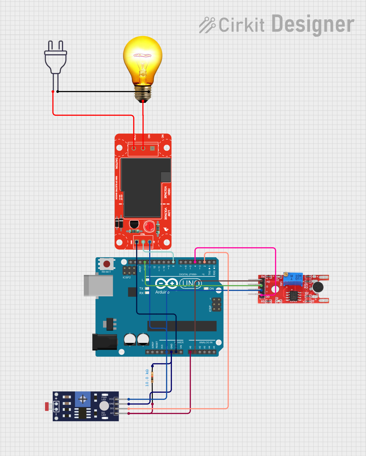
Circuit Documentation
Summary
The circuit is designed to detect specific frequencies of sound using a KY-038 sound sensor and control an AC bulb through a relay module based on the detected frequency. The Arduino UNO serves as the central processing unit, reading the analog signals from the sound sensor and the photoresistor sensor, and controlling the relay module accordingly. The relay module switches the AC bulb on or off, and the photoresistor sensor provides additional input that could be used for light-based control logic. A resistor is included for potential voltage division or current limiting purposes.
Component List
Arduino UNO
- Microcontroller board based on the ATmega328P.
- It has 14 digital input/output pins, 6 analog inputs, a 16 MHz quartz crystal, a USB connection, a power jack, an ICSP header, and a reset button.
Resistor (10k Ohms)
- A passive two-terminal electrical component that implements electrical resistance as a circuit element.
Photoresistor (LDR) Sensor (Wokwi Compatible)
- A light-controlled variable resistor. The resistance of a photoresistor decreases with increasing incident light intensity.
SparkFun Beefcake Relay Control Kit
- A relay module capable of switching AC loads. It features a single pole double throw (SPDT) relay.
AC Bulb
- An electric light with a wire filament heated until it glows. It is designed for use with an AC power source.
Power 220V
- A power source providing 220V AC, typically used for mains electricity.
KY-038 Sound Sensor Module
- A sound detection sensor module that features a microphone and a digital output.
Wiring Details
Arduino UNO
5Vconnected to KY-038+, PhotoresistorVCC, and Relay ModuleVCC.GNDconnected to Resistorpin2, PhotoresistorGND, Relay ModuleGND, and KY-038G.A0connected to Resistorpin1and PhotoresistorAO.A1connected to KY-038A0.D2connected to PhotoresistorDO.D4connected to KY-038D0.D8connected to Relay ModuleRELAY.
Resistor (10k Ohms)
pin1connected to Arduino UNOA0.pin2connected to Arduino UNOGND.
Photoresistor (LDR) Sensor (Wokwi Compatible)
VCCconnected to Arduino UNO5V.GNDconnected to Arduino UNOGND.DOconnected to Arduino UNOD2.AOconnected to Arduino UNOA0.
SparkFun Beefcake Relay Control Kit
VCCconnected to Arduino UNO5V.GNDconnected to Arduino UNOGND.RELAYconnected to Arduino UNOD8.NOconnected to AC BulbP.COMMONconnected to Power 220Vhot wire.
AC Bulb
Pconnected to Relay ModuleNO.Nconnected to Power 220Vneutral wire.
Power 220V
hot wireconnected to Relay ModuleCOMMON.neutral wireconnected to AC BulbN.
KY-038 Sound Sensor Module
+connected to Arduino UNO5V.Gconnected to Arduino UNOGND.A0connected to Arduino UNOA1.D0connected to Arduino UNOD4.
Documented Code
#include <ArduinoFFT.h>

#define SOUND_SENSOR_PIN A0  // Analog pin connected to the sound sensor
#define RELAY_PIN 8          // Digital pin connected to the relay module

const uint16_t samples = 128; // Must be a power of 2
const double samplingFrequency = 1000; // Hz, must be less than 10000 due to ADC

unsigned int sampling_period_us;
unsigned long microseconds;

double vReal[samples];     // Real part of the signal
double vImag[samples];     // Imaginary part of the signal

ArduinoFFT FFT = ArduinoFFT(); // Create FFT object

void setup() {
  Serial.begin(9600); // Start serial communication at 9600 baud rate

  pinMode(RELAY_PIN, OUTPUT); // Set the relay pin as an output
  digitalWrite(RELAY_PIN, LOW); // Ensure the relay is off initially

  sampling_period_us = round(1000000 * (1.0 / samplingFrequency)); // Calculate the sampling period
}

void loop() {
  /* Sample the signal */
  for (int i = 0; i < samples; i++) {
    microseconds = micros();

    vReal[i] = analogRead(SOUND_SENSOR_PIN); // Read the analog input and store it in the vReal array
    vImag[i] = 0; // Initialize the vImag array with zeros

    while (micros() - microseconds < sampling_period_us) {
      // Do nothing to wait for the next sample time
    }
  }

  /* Compute FFT */
  FFT.Compute(vReal, vImag, samples, FFT_FORWARD); // Compute the FFT
  FFT.ComplexToMagnitude(vReal, vImag, samples); // Convert complex numbers to magnitudes

  /* Find the peak frequency */
  double peakFrequency = FFT.MajorPeak(vReal, samples, samplingFrequency);

  /* Print the peak frequency to the Serial Monitor */
  Serial.print("Peak Frequency: ");
  Serial.println(peakFrequency);

  /* Check if the peak frequency is within the clap frequency range */
  double lowerThreshold = 1000.0; // Lower frequency threshold (in Hz)
  double upperThreshold = 2000.0; // Upper frequency threshold (in Hz)

  if (peakFrequency >= lowerThreshold && peakFrequency <= upperThreshold) {
    // Frequency is within range, turn on the relay
    digitalWrite(RELAY_PIN, HIGH);
    Serial.println("Relay ON");
  } else {
    // Frequency is outside range, turn off the relay
    digitalWrite(RELAY_PIN, LOW);
    Serial.println("Relay OFF");
  }

  // Wait a short while before sampling again
  delay(100);
}
This code is designed to run on the Arduino UNO. It uses the ArduinoFFT library to perform a Fast Fourier Transform (FFT) on the signal from the sound sensor. The code samples the sound sensor at a specified frequency, computes the FFT, and then finds the peak frequency. If the peak frequency is within a specified range, it turns on a relay, which could be used to control an AC bulb or other device. The relay is turned off if the frequency is outside the specified range.