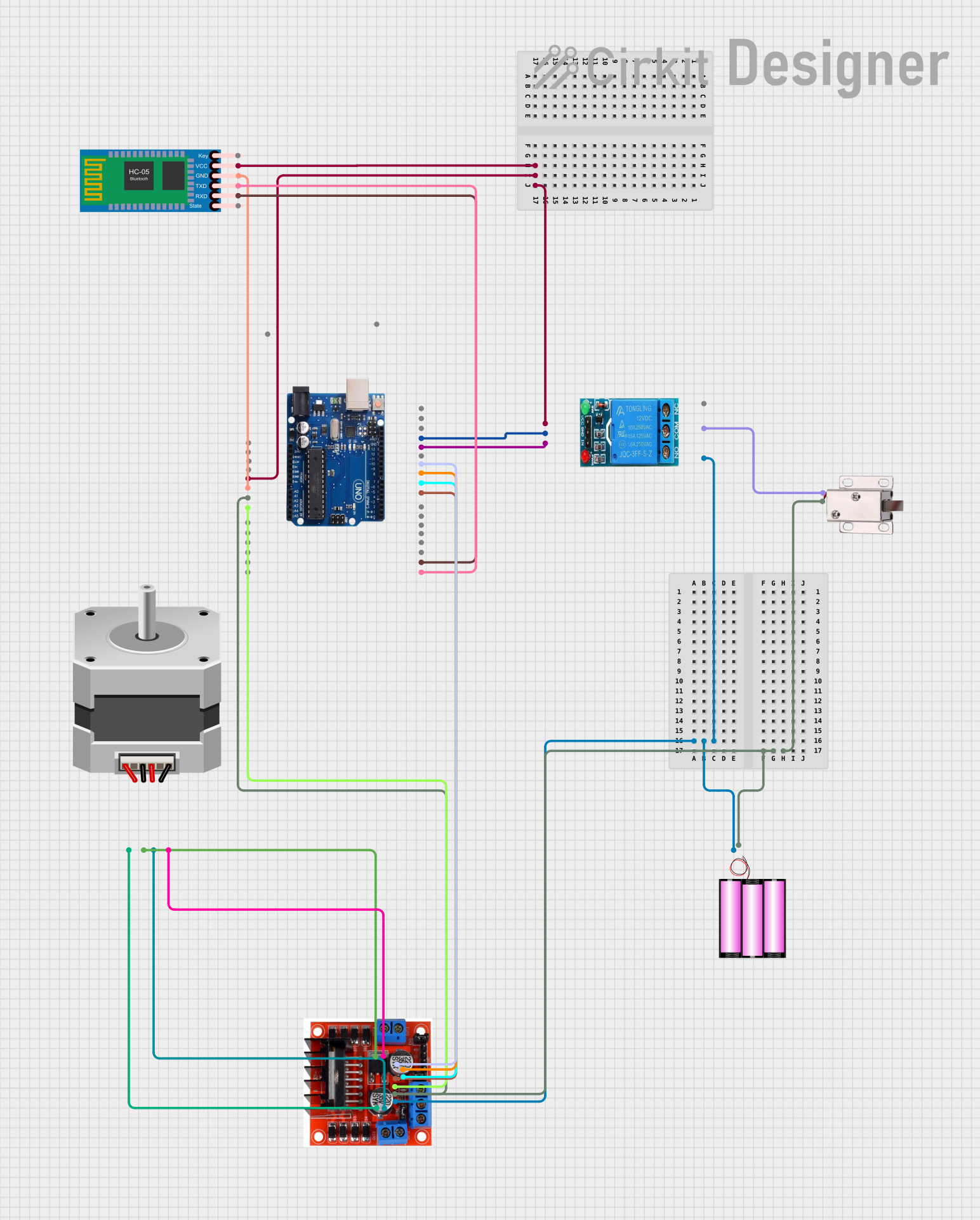
Arduino-Controlled Bluetooth Stepper Motor with Solenoid Lock and Relay Switching

Circuit Documentation
Summary
This circuit is designed to control a NEMA23 stepper motor using an Arduino Uno R3 as the main microcontroller. The circuit includes an L298N Motor Driver to interface with the stepper motor, a 12V battery to power the motor and the motor driver, and a 5V single-channel relay to control a 12V solenoid lock. Additionally, an HC-05 Bluetooth Module is incorporated for wireless communication, possibly for remote control or data transmission purposes.
Component List
Arduino Uno R3
- Microcontroller board based on the ATmega328P
- Features digital I/O pins, analog input pins, and various power pins
NEMA23
- A stepper motor commonly used for high torque applications
L298N Motor Driver Controller Board Module
- A dual H-bridge motor driver capable of driving a pair of DC motors or one stepper motor
5V Single Channel Relay
- An electromechanical switch used to control a high power circuit with a low power signal
12V Battery
- Provides power to the circuit
12V Solenoid Lock
- An electrically-controlled lock mechanism
HC-05 Bluetooth Module
- A wireless communication module for Bluetooth connectivity
Wiring Details
Arduino Uno R3
5Vconnected to HC-05 Bluetooth ModuleVCCand 5V Single Channel RelayVCCGNDconnected to HC-05 Bluetooth ModuleGND, L298N Motor DriverGround, and 5V Single Channel RelayGNDVINconnected to L298N Motor Driver+5v Power- Digital pins
13,11,10,9, and8connected to 5V Single Channel RelayINand L298N Motor DriverInput 4,Input 3,Input 2, andInput 1respectively RXandTX(pins0and1) connected to HC-05 Bluetooth ModuleTXDandRXD
NEMA23
- Pins
A,B,C, andDconnected to L298N Motor DriverOutput AandOutput B
L298N Motor Driver Controller Board Module
+12v Powerconnected to 12V Battery+and 5V Single Channel RelayNO+5v Powerconnected to Arduino Uno R3VINGroundconnected to Arduino Uno R3GNDOutput AandOutput Bconnected to NEMA23Input 1,Input 2,Input 3, andInput 4connected to Arduino Uno R3 digital pins8,9,10, and11
5V Single Channel Relay
VCCconnected to Arduino Uno R35VGNDconnected to Arduino Uno R3GNDINconnected to Arduino Uno R3 pin13NOconnected to L298N Motor Driver+12v PowerCOMconnected to 12V Solenoid LockVCC
12V Battery
+connected to L298N Motor Driver+12v Power-connected to L298N Motor DriverGround, 12V Solenoid LockGND, and Arduino Uno R3GND
12V Solenoid Lock
VCCconnected to 5V Single Channel RelayCOMGNDconnected to 12V Battery-
HC-05 Bluetooth Module
VCCconnected to Arduino Uno R35VGNDconnected to Arduino Uno R3GNDTXDconnected to Arduino Uno R3RX(pin0)RXDconnected to Arduino Uno R3TX(pin1)
Documented Code
No code has been provided for the microcontroller. The expected code should handle the communication with the HC-05 Bluetooth Module, control the L298N Motor Driver to operate the NEMA23 stepper motor, and manage the state of the 5V Single Channel Relay to lock or unlock the 12V Solenoid Lock based on the received Bluetooth commands.