
Circuit Documentation
Summary
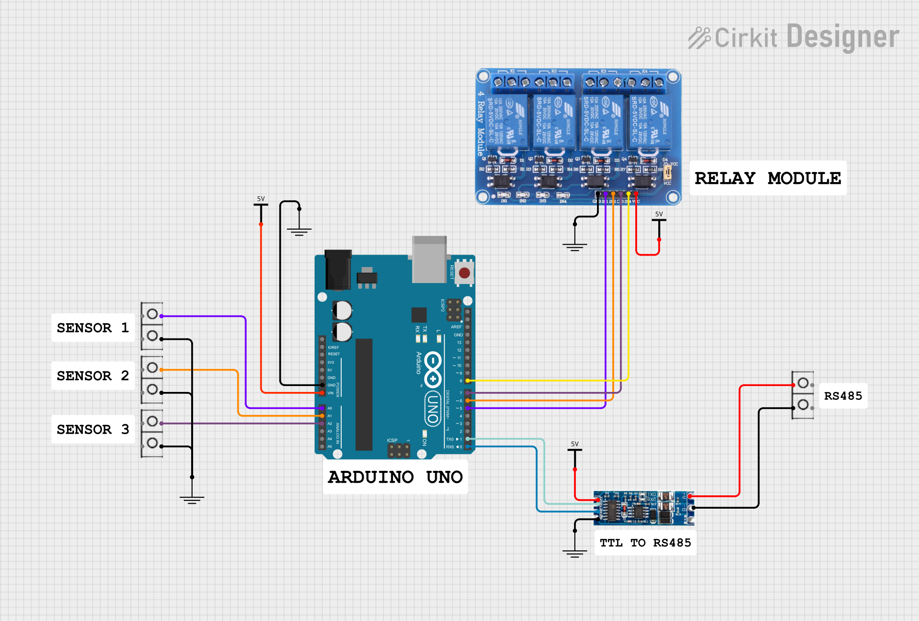
This circuit involves an Arduino UNO microcontroller interfacing with a UART TTL to RS485 converter and a 4-channel relay module. The circuit also includes several wire connectors and power supply components (Vcc and GND). The Arduino UNO is programmed to control the relays and communicate via the RS485 protocol.
Component List
Arduino UNO
- Pins: UNUSED, IOREF, Reset, 3.3V, 5V, GND, Vin, A0, A1, A2, A3, A4, A5, SCL, SDA, AREF, D13, D12, D11, D10, D9, D8, D7, D6, D5, D4, D3, D2, D1, D0
- Description: A microcontroller board based on the ATmega328P.
- Purpose: Central control unit for the circuit.
UART TTL to RS485 Two-way Converter
- Pins: VCC, TXD, RXD, GND, A, B
- Description: Converts UART TTL signals to RS485 and vice versa.
- Purpose: Enables RS485 communication.
Relay 4 Channel 5v
- Pins: GND, IN1, IN2, IN3, IN4, VCC, COM1, COM2, COM3, COM4, NO1, NO2, NO3, NO4, NC1, NC2, NC3, NC4
- Description: A relay module with 4 channels, each capable of switching loads.
- Purpose: Controls high-power devices.
GND
- Pins: GND
- Description: Ground connection.
- Purpose: Provides a common ground reference.
Vcc
- Pins: Vcc
- Description: Power supply connection.
- Purpose: Provides power to the circuit.
Wire Connector
- Pins: +, -
- Description: Connects wires in the circuit.
- Purpose: Facilitates connections between components.
Wiring Details
Arduino UNO
- GND connected to GND of GND component.
- Vin connected to Vcc of Vcc component.
- A0 connected to + of wire connector.
- A1 connected to + of another wire connector.
- A2 connected to + of another wire connector.
- D8 connected to IN4 of Relay 4 Channel 5v.
- D7 connected to IN3 of Relay 4 Channel 5v.
- D6 connected to IN2 of Relay 4 Channel 5v.
- D5 connected to IN1 of Relay 4 Channel 5v.
- D1 connected to TXD of UART TTL to RS485 Two-way Converter.
- D0 connected to RXD of UART TTL to RS485 Two-way Converter.
UART TTL to RS485 Two-way Converter
- VCC connected to Vcc of Vcc component.
- GND connected to GND of GND component.
- A connected to + of wire connector.
- B connected to - of wire connector.
Relay 4 Channel 5v
- GND connected to GND of GND component.
- VCC connected to Vcc of Vcc component.
- IN4 connected to D8 of Arduino UNO.
- IN3 connected to D7 of Arduino UNO.
- IN2 connected to D6 of Arduino UNO.
- IN1 connected to D5 of Arduino UNO.
GND
- GND connected to GND of Arduino UNO.
- GND connected to GND of UART TTL to RS485 Two-way Converter.
- GND connected to GND of Relay 4 Channel 5v.
Vcc
- Vcc connected to Vin of Arduino UNO.
- Vcc connected to VCC of UART TTL to RS485 Two-way Converter.
- Vcc connected to VCC of Relay 4 Channel 5v.
Wire Connector
- + connected to A0 of Arduino UNO.
- + connected to A1 of Arduino UNO.
- + connected to A2 of Arduino UNO.
- + connected to A of UART TTL to RS485 Two-way Converter.
- - connected to B of UART TTL to RS485 Two-way Converter.
- - connected to - of another wire connector.
- - connected to - of another wire connector.
- - connected to GND of GND component.
Documented Code
Arduino UNO Code (sketch.ino)
void setup() {
  // put your setup code here, to run once:

}

void loop() {
  // put your main code here, to run repeatedly:

}
Additional Documentation (documentation.txt)
This documentation provides a comprehensive overview of the circuit, including a summary, detailed component list, wiring details, and the code used in the Arduino UNO microcontroller.