Cirkit Designer
Your all-in-one circuit design IDE
Home /
Project Documentation
Arduino UNO Based Multi-Flame Sensor Monitoring System
Circuit Documentation
Summary
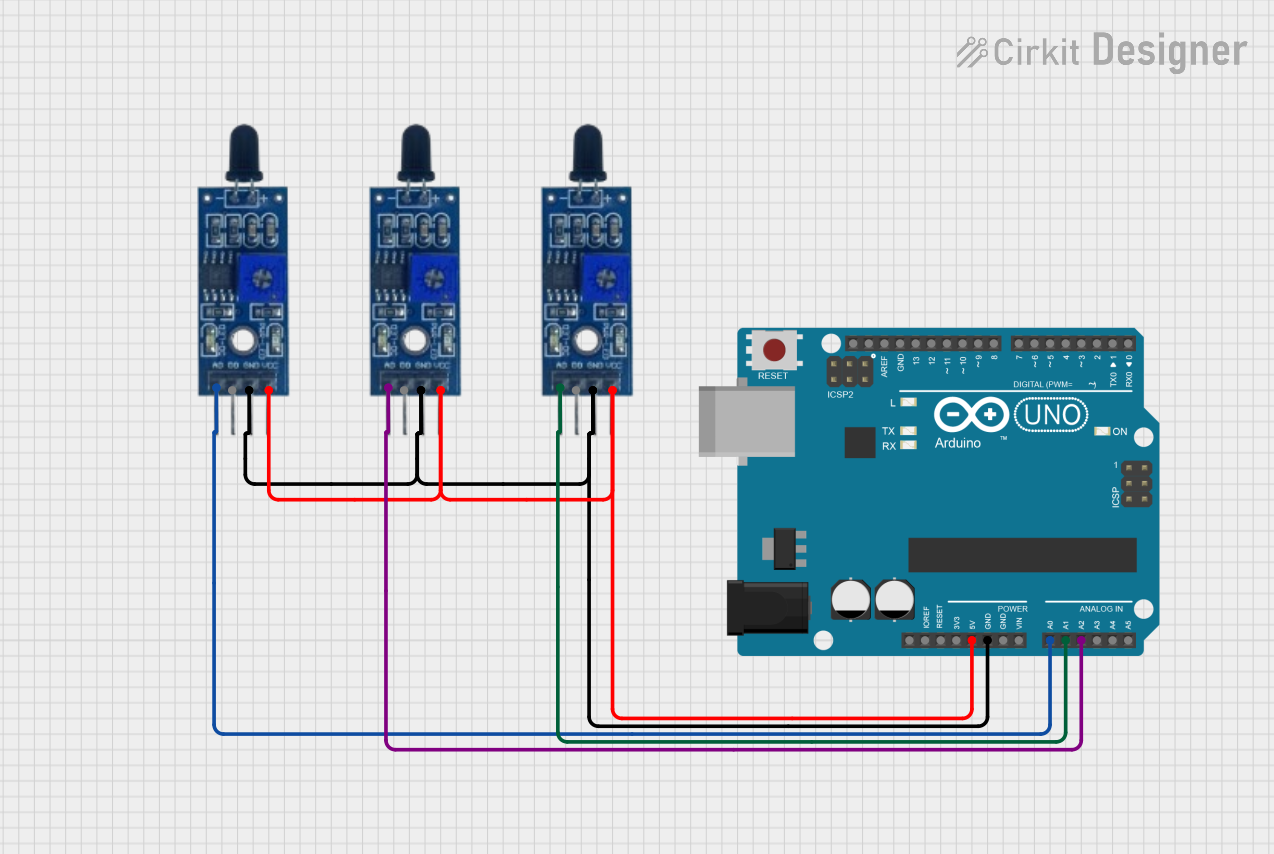
This circuit integrates an Arduino UNO microcontroller with three flame sensors to detect the presence of flames in different locations. The flame sensors are connected to the Arduino UNO to read analog values representing the intensity of the detected flames. The Arduino UNO is programmed to read the analog inputs from the flame sensors and output the readings through the serial interface.
Component List
Arduino UNO
- Description: A microcontroller board based on the ATmega328P.
- Purpose: Acts as the central processing unit of the circuit, reading sensor data and providing power to the flame sensors.
- Pins: UNUSED, IOREF, Reset, 3.3V, 5V, GND, Vin, A0-A5, SCL, SDA, AREF, D0-D13.
Flame Sensor (x3)
- Description: A sensor that detects the presence of a flame or fire.
- Purpose: To detect varying levels of flame intensity and provide an analog output.
- Pins: VCC, GND, D0, A0.
Wiring Details
Arduino UNO
- 5V: Provides power to all three flame sensors.
- GND: Connected to the ground pins of all three flame sensors.
- A0: Reads the analog output from the first flame sensor.
- A1: Reads the analog output from the second flame sensor.
- A2: Reads the analog output from the third flame sensor.
Flame Sensor 1
- VCC: Connected to the 5V output on the Arduino UNO.
- GND: Connected to the ground on the Arduino UNO.
- A0: Analog output connected to the A0 pin on the Arduino UNO.
Flame Sensor 2
- VCC: Connected to the 5V output on the Arduino UNO.
- GND: Connected to the ground on the Arduino UNO.
- A0: Analog output connected to the A1 pin on the Arduino UNO.
Flame Sensor 3
- VCC: Connected to the 5V output on the Arduino UNO.
- GND: Connected to the ground on the Arduino UNO.
- A0: Analog output connected to the A2 pin on the Arduino UNO.
Documented Code
void setup() {
  // Initialize serial communication at 9600 bits per second:
  Serial.begin(9600);

  // Set up the analog pins for input:
  pinMode(A0, INPUT);
  pinMode(A1, INPUT);
  pinMode(A2, INPUT);
}

void loop() {
  // Read the input on analog pins A0, A1, and A2:
  int sensorValue0 = analogRead(A0);
  int sensorValue1 = analogRead(A1);
  int sensorValue2 = analogRead(A2);

  // Print out the values you read:
  Serial.print("Sensor 0: ");
  Serial.println(sensorValue0);
  Serial.print("Sensor 1: ");
  Serial.println(sensorValue1);
  Serial.print("Sensor 2: ");
  Serial.println(sensorValue2);

  // Delay a bit for stability:
  delay(1000);
}
Filename: sketch.ino
Description: This code initializes the serial communication and configures the analog pins A0, A1, and A2 as inputs. In the main loop, it reads the analog values from the flame sensors and prints them to the serial monitor every second.