
ESP8266 NodeMCU Controlled Water Flow System with Dual Relay Pump Activation
View and Edit Project In Cirkit Designer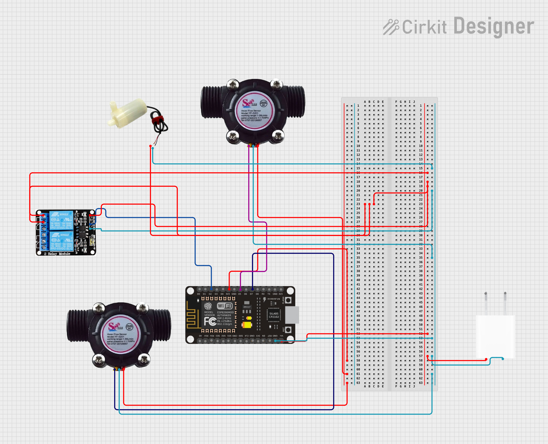
Circuit Documentation
Summary
The circuit in question appears to be designed for controlling a water flow system using an ESP8266 NodeMCU microcontroller. The system includes a 5V 2-Relay module to switch a mini water pump on and off, a 5V power adapter to supply power to the circuit, and two water flow sensors to monitor the flow of water.
Component List
ESP8266 NodeMCU
- Microcontroller with WiFi capability.
- Pins: D0, D1, D2, D3, D4, 3V3, GND, D5, D6, D7, D8, RX, TX, A0, RSV, SD3, SD2, SD1, CMD, SD0, CLK, EN, RST, VIN.
5V 2-Relay Module (JD-VCC)
- A module with two relays capable of controlling high power devices.
- Pins: JD-VCC, VCC, GND, IN1, IN2, NO, COM, NC.
5V Adapter
- Power supply adapter that converts AC to 5V DC.
- Pins: AC In 1, AC In 2, 5V, GND.
Water Flow Sensor
- A sensor that measures the flow rate of water.
- Pins: Signal, Vcc, GND.
5V Mini Water Pump
- A pump that operates on 5V to pump water.
- Pins: Positive pin, Negative pin.
Wiring Details
ESP8266 NodeMCU
- VIN connected to 5V Adapter (5V output).
- GND connected to 5V Adapter (GND), Water Flow Sensor (GND), and 5V 2-Relay Module (GND).
- 3V3 connected to both Water Flow Sensors (Vcc).
- D2 connected to 5V 2-Relay Module (IN1).
- D5 connected to Water Flow Sensor (Signal).
- D7 connected to Water Flow Sensor (Signal).
5V 2-Relay Module (JD-VCC)
- NO connected to 5V Mini Water Pump (Positive pin).
- COM connected to itself (loopback for relay configuration).
- VCC connected to ESP8266 NodeMCU (VIN).
- GND connected to 5V Adapter (GND), Water Flow Sensor (GND), and ESP8266 NodeMCU (GND).
5V Adapter
- 5V output connected to ESP8266 NodeMCU (VIN).
- GND connected to ESP8266 NodeMCU (GND), Water Flow Sensor (GND), and 5V 2-Relay Module (GND).
Water Flow Sensor
- Signal connected to ESP8266 NodeMCU (D5 and D7).
- Vcc connected to ESP8266 NodeMCU (3V3).
- GND connected to ESP8266 NodeMCU (GND).
5V Mini Water Pump
- Positive pin connected to 5V 2-Relay Module (NO).
- Negative pin connected to 5V 2-Relay Module (GND).
Documented Code
No code was provided for the microcontroller. The expected functionality would include reading the water flow sensor data through the digital pins D5 and D7, and controlling the relay module via pin D2 to turn the water pump on or off based on the sensor readings or other logic. Without the code, the specific operation of the microcontroller cannot be documented.