
Arduino UNO and Bluetooth-Controlled Servo Motor System with PWM Driver
View and Edit Project In Cirkit Designer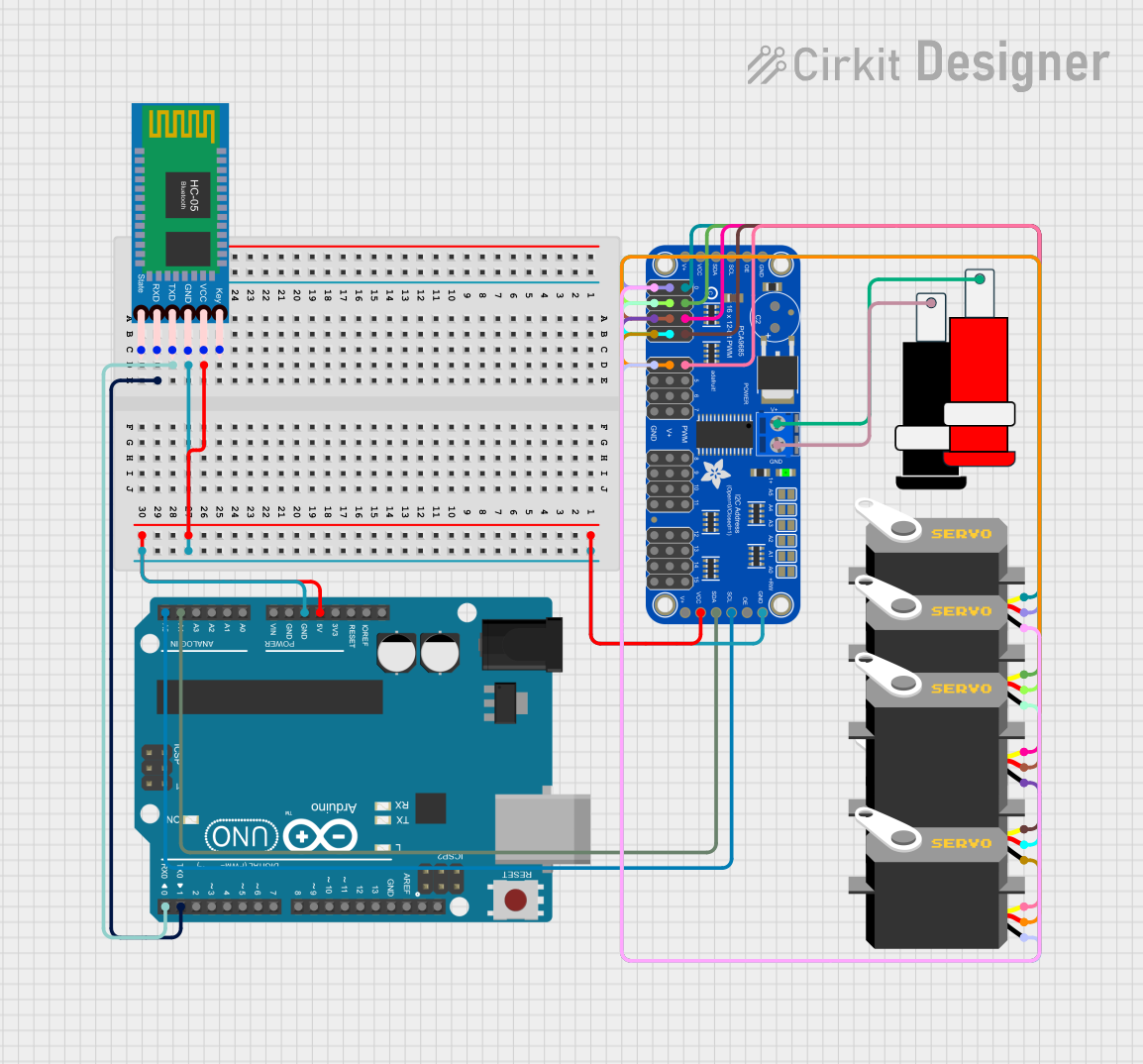
Circuit Documentation
Summary
This circuit involves an Arduino UNO microcontroller, an Adafruit 16-Channel 12-bit PWM Servo Driver, multiple servos, an HC-05 Bluetooth Module, and a 5V power connector. The Arduino UNO is used to control the servos via the PWM driver, and the Bluetooth module allows for wireless communication. The 5V power connector supplies power to the circuit.
Component List
Arduino UNO
- Description: A microcontroller board based on the ATmega328P.
- Pins: UNUSED, IOREF, Reset, 3.3V, 5V, GND, Vin, A0, A1, A2, A3, A4, A5, SCL, SDA, AREF, D13, D12, D11, D10, D9, D8, D7, D6, D5, D4, D3, D2, D1, D0
Adafruit 16-Channel 12-bit PWM Servo Driver - I2C
- Description: A PWM driver that can control up to 16 servos or LEDs over I2C.
- Pins: 5.0V, VCC, SDA, SCL, OE, GND, PWM0, PWM1, PWM2, PWM3, PWM4, PWM5, PWM6, PWM7, PWRIN, PWM8, PWM9, PWM10, PWM11, PWM12, PWM13, PWM14, PWM15
Connector 5V
- Description: A connector to supply 5V power to the circuit.
- Pins: GND, VCC
Servo
- Description: A standard servo motor.
- Pins: gnd, vcc, pulse
HC-05 Bluetooth Module
- Description: A Bluetooth module for wireless communication.
- Pins: Key, VCC, TXD, RXD, State, GND
Wiring Details
Arduino UNO
- 5V connected to VCC of HC-05 Bluetooth Module and Adafruit 16-Channel 12-bit PWM Servo Driver.
- GND connected to GND of HC-05 Bluetooth Module and Adafruit 16-Channel 12-bit PWM Servo Driver.
- D0 connected to TXD of HC-05 Bluetooth Module.
- D1 connected to RXD of HC-05 Bluetooth Module.
- A4 connected to SDA of Adafruit 16-Channel 12-bit PWM Servo Driver.
- A5 connected to SCL of Adafruit 16-Channel 12-bit PWM Servo Driver.
Adafruit 16-Channel 12-bit PWM Servo Driver - I2C
- VCC connected to 5V of Arduino UNO and HC-05 Bluetooth Module.
- GND connected to GND of Arduino UNO and HC-05 Bluetooth Module.
- SDA connected to A4 of Arduino UNO.
- SCL connected to A5 of Arduino UNO.
- PWRIN connected to VCC of Connector 5V.
- GND connected to GND of Connector 5V.
- PWM0 connected to pulse of Servo 1.
- PWM1 connected to pulse of Servo 2.
- PWM2 connected to pulse of Servo 3.
- PWM3 connected to pulse of Servo 4.
- PWM4 connected to pulse of Servo 5.
- 5.0V connected to vcc of all Servos.
- GND connected to gnd of all Servos.
Connector 5V
- VCC connected to PWRIN of Adafruit 16-Channel 12-bit PWM Servo Driver.
- GND connected to GND of Adafruit 16-Channel 12-bit PWM Servo Driver.
Servo 1
- gnd connected to GND of Adafruit 16-Channel 12-bit PWM Servo Driver.
- vcc connected to 5.0V of Adafruit 16-Channel 12-bit PWM Servo Driver.
- pulse connected to PWM0 of Adafruit 16-Channel 12-bit PWM Servo Driver.
Servo 2
- gnd connected to GND of Adafruit 16-Channel 12-bit PWM Servo Driver.
- vcc connected to 5.0V of Adafruit 16-Channel 12-bit PWM Servo Driver.
- pulse connected to PWM1 of Adafruit 16-Channel 12-bit PWM Servo Driver.
Servo 3
- gnd connected to GND of Adafruit 16-Channel 12-bit PWM Servo Driver.
- vcc connected to 5.0V of Adafruit 16-Channel 12-bit PWM Servo Driver.
- pulse connected to PWM2 of Adafruit 16-Channel 12-bit PWM Servo Driver.
Servo 4
- gnd connected to GND of Adafruit 16-Channel 12-bit PWM Servo Driver.
- vcc connected to 5.0V of Adafruit 16-Channel 12-bit PWM Servo Driver.
- pulse connected to PWM3 of Adafruit 16-Channel 12-bit PWM Servo Driver.
Servo 5
- gnd connected to GND of Adafruit 16-Channel 12-bit PWM Servo Driver.
- vcc connected to 5.0V of Adafruit 16-Channel 12-bit PWM Servo Driver.
- pulse connected to PWM4 of Adafruit 16-Channel 12-bit PWM Servo Driver.
HC-05 Bluetooth Module
- VCC connected to 5V of Arduino UNO.
- GND connected to GND of Arduino UNO.
- TXD connected to D0 of Arduino UNO.
- RXD connected to D1 of Arduino UNO.
Code Documentation
Arduino UNO Code
sketch.ino
void setup() {
  // put your setup code here, to run once:

}

void loop() {
  // put your main code here, to run repeatedly:

}
documentation.txt