
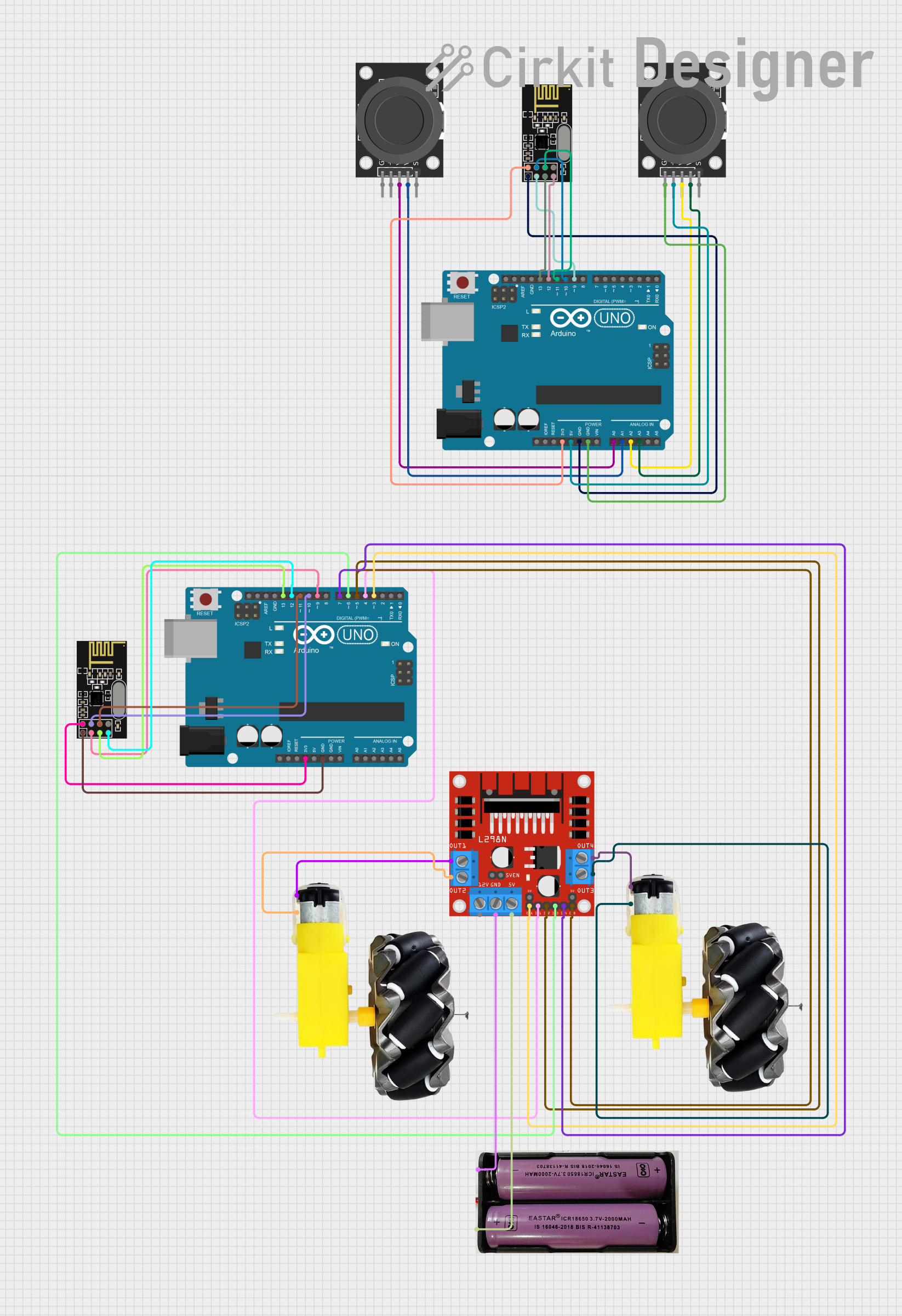
Circuit Documentation
Summary
This circuit consists of two Arduino UNO microcontrollers, two NRF24L01 wireless transceivers, two KY-023 Dual Axis Joystick Modules, an L298N DC motor driver, and two motor and wheel assemblies. The circuit is designed to read joystick inputs and wirelessly transmit the data to control the motors.
Component List
KY-023 Dual Axis Joystick Module
- Pins: GND, +5V, VRx, VRy, SW
- Description: A joystick module that provides analog output for X and Y axes and a digital output for the switch.
NRF24L01
- Pins: IRQ (not used), MOSI, CSN, VCC (3V), GND, CE, SCK, MISO
- Description: A wireless transceiver module used for communication between the two Arduino UNOs.
Arduino UNO
- Pins: UNUSED, IOREF, Reset, 3.3V, 5V, GND, Vin, A0, A1, A2, A3, A4, A5, SCL, SDA, AREF, D13, D12, D11, D10, D9, D8, D7, D6, D5, D4, D3, D2, D1, D0
- Description: A microcontroller board based on the ATmega328P.
L298N DC Motor Driver
- Pins: OUT1, OUT2, 12V, GND, 5V, OUT3, OUT4, 5V-ENA-JMP-I, 5V-ENA-JMP-O, +5V-J1, +5V-J2, ENA, IN1, IN2, IN3, IN4, ENB
- Description: A dual H-bridge motor driver module that allows control of the speed and direction of two DC motors.
Motor and Wheels
- Pins: vcc, GND
- Description: A motor and wheel assembly used for movement.
7.4V Battery
- Pins: +, -
- Description: A power source for the motor driver.
Wiring Details
KY-023 Dual Axis Joystick Module (Joystick 1)
- GND connected to Arduino UNO GND
- +5V connected to Arduino UNO 5V
- VRx connected to Arduino UNO A0
- VRy connected to Arduino UNO A1
KY-023 Dual Axis Joystick Module (Joystick 2)
- GND connected to Arduino UNO GND
- +5V connected to Arduino UNO 5V
- VRx connected to Arduino UNO A2
- VRy connected to Arduino UNO A3
NRF24L01 (Transceiver 1)
- VCC (3V) connected to Arduino UNO 3.3V
- GND connected to Arduino UNO GND
- SCK connected to Arduino UNO D13
- MISO connected to Arduino UNO D12
- MOSI connected to Arduino UNO D11
- CSN connected to Arduino UNO D10
- CE connected to Arduino UNO D9
NRF24L01 (Transceiver 2)
- VCC (3V) connected to Arduino UNO 3.3V
- GND connected to Arduino UNO GND
- SCK connected to Arduino UNO D13
- MISO connected to Arduino UNO D12
- MOSI connected to Arduino UNO D11
- CSN connected to Arduino UNO D10
- CE connected to Arduino UNO D9
L298N DC Motor Driver
- IN1 connected to Arduino UNO D4
- IN2 connected to Arduino UNO D5
- IN3 connected to Arduino UNO D6
- IN4 connected to Arduino UNO D7
- ENA connected to Arduino UNO D3
- ENB connected to Arduino UNO D5
- OUT1 connected to Motor and Wheels vcc
- OUT2 connected to Motor and Wheels GND
- OUT3 connected to Motor and Wheels GND
- OUT4 connected to Motor and Wheels vcc
- GND connected to 7.4V Battery -
- 5V connected to 7.4V Battery +
Motor and Wheels (Motor 1)
- vcc connected to L298N DC Motor Driver OUT1
- GND connected to L298N DC Motor Driver OUT2
Motor and Wheels (Motor 2)
- vcc connected to L298N DC Motor Driver OUT4
- GND connected to L298N DC Motor Driver OUT3
7.4V Battery
- + connected to L298N DC Motor Driver 5V
- - connected to L298N DC Motor Driver GND
Documented Code
Arduino UNO (Transmitter)
#include <SPI.h>
#include <nRF24L01.h>
#include <RF24.h>

RF24 radio(9, 10);  // CE, CSN pins
const byte address[6] = "00001";

void setup() {
  radio.begin();
  radio.openWritingPipe(address);
  radio.setPALevel(RF24_PA_LOW);
  radio.stopListening();
}

void loop() {
  int joystick1_x = analogRead(A0);  // Read joystick 1 X-axis
  int joystick1_y = analogRead(A1);  // Read joystick 1 Y-axis
  int joystick2_x = analogRead(A2);  // Read joystick 2 X-axis
  int joystick2_y = analogRead(A3);  // Read joystick 2 Y-axis

  int data[] = {joystick1_x, joystick1_y, joystick2_x, joystick2_y};
  radio.write(&data, sizeof(data));  // Transmit joystick data
  delay(50);
}
Arduino UNO (Receiver)
#include <SPI.h>
#include <nRF24L01.h>
#include <RF24.h>

RF24 radio(9, 10);  // CE, CSN pins
const byte address[6] = "00001";

int motor1_pwm = 3;  // Motor 1 PWM pin
int motor1_dir = 4;  // Motor 1 Direction pin
int motor2_pwm = 5;  // Motor 2 PWM pin
int motor2_dir = 6;  // Motor 2 Direction pin

void setup() {
  radio.begin();
  radio.openReadingPipe(0, address);
  radio.setPALevel(RF24_PA_LOW);
  radio.startListening();

  pinMode(motor1_pwm, OUTPUT);
  pinMode(motor1_dir, OUTPUT);
  pinMode(motor2_pwm, OUTPUT);
  pinMode(motor2_dir, OUTPUT);
}

void loop() {
  if (radio.available()) {
    int data[4];
    radio.read(&data, sizeof(data));  // Receive joystick data

    int joystick1_x = data[0];
    int joystick1_y = data[1];
    int joystick2_x = data[2];
    int joystick2_y = data[3];

    // Map joystick values to motor control
    int motor1_speed = map(joystick1_y, 0, 1023, -255, 255);
    int motor2_speed = map(joystick2_y, 0, 1023, -255, 255);

    // Control motor 1
    analogWrite(motor1_pwm, abs(motor1_speed));
    digitalWrite(motor1_dir, motor1_speed > 0);

    // Control motor 2
    analogWrite(motor2_pwm, abs(motor2_speed));
    digitalWrite(motor2_dir, motor2_speed > 0);
  }
}