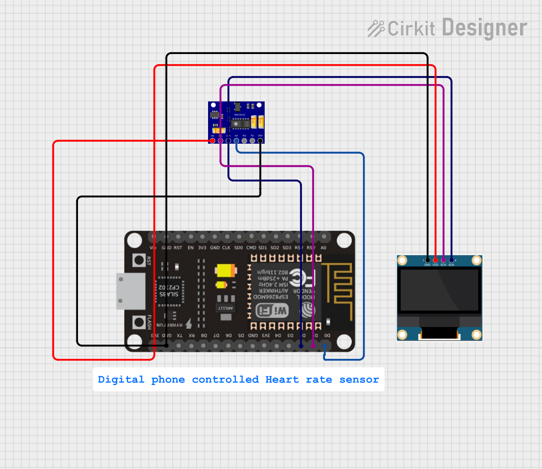
ESP-8266 Based Heart Rate and Oxygen Level Monitor with OLED Display

Circuit Documentation
Summary
The circuit in question is designed to monitor heart rate and oxygen saturation levels using a MAX30102 sensor, display the data on a 0.96" OLED screen, and is controlled by an ESP-8266 microcontroller. The ESP-8266 manages the data processing and communication with the sensor and the OLED display. The circuit is powered by a 3.3V supply from the ESP-8266, which is distributed to the other components. Communication between the microcontroller, sensor, and display is achieved through the I2C protocol, utilizing the SDA and SCL lines.
Component List
0.96" OLED
- Description: A small OLED display used for visual output of data such as heart rate and oxygen saturation levels.
- Pins: GND, VDD, SCK, SDA
MAX30102 Heart Rate and Oxygen Sensor
- Description: A sensor used to measure heart rate and blood oxygen levels.
- Pins: VIN, SCL, SDA, INT, IRQ, RD, GND
ESP-8266 Controller
- Description: A microcontroller with Wi-Fi capabilities, used as the main processing unit for controlling the OLED display and reading data from the MAX30102 sensor.
- Pins: A0, RSV, SD3, SD5, SD1, CMD, D0, D1, D2, D3, D4, 3V3, GND, D5, D6, SD0, CLK, RST, EN, D7, D8, RX, TX, Vin, 5V
Comment
- Description: This component is a placeholder and does not have a physical representation in the circuit.
Wiring Details
0.96" OLED
- GND: Connected to the ground (GND) of the ESP-8266 Controller.
- VDD: Connected to the 3.3V power supply (3V3) of the ESP-8266 Controller.
- SCK: Connected to the serial clock line (D1) of the ESP-8266 Controller.
- SDA: Connected to the serial data line (D2) of the ESP-8266 Controller.
MAX30102 Heart Rate and Oxygen Sensor
- VIN: Connected to the 3.3V power supply (3V3) of the ESP-8266 Controller.
- SCL: Connected to the serial clock line (D1) of the ESP-8266 Controller.
- SDA: Connected to the serial data line (D2) of the ESP-8266 Controller.
- INT: Connected to the digital input/output (D0) of the ESP-8266 Controller.
- GND: Connected to the ground (GND) of the ESP-8266 Controller.
ESP-8266 Controller
- 3V3: Provides power to the OLED display and the MAX30102 sensor.
- GND: Common ground for the circuit.
- D1 (SCL): Serial clock line for I2C communication with the OLED display and MAX30102 sensor.
- D2 (SDA): Serial data line for I2C communication with the OLED display and MAX30102 sensor.
- D0: Connected to the interrupt pin (INT) of the MAX30102 sensor.
Documented Code
No code has been provided for the microcontroller. The expected code should initialize the I2C communication, set up the MAX30102 sensor, handle the data reading, process the data, and display the results on the OLED screen. Additionally, the code should manage the interrupt-driven events from the MAX30102 sensor.
Please provide the code for the ESP-8266 microcontroller to complete the documentation.