
Rain Sensor Controlled Gearmotor with 5V Relay and Battery Power
View and Edit Project In Cirkit Designer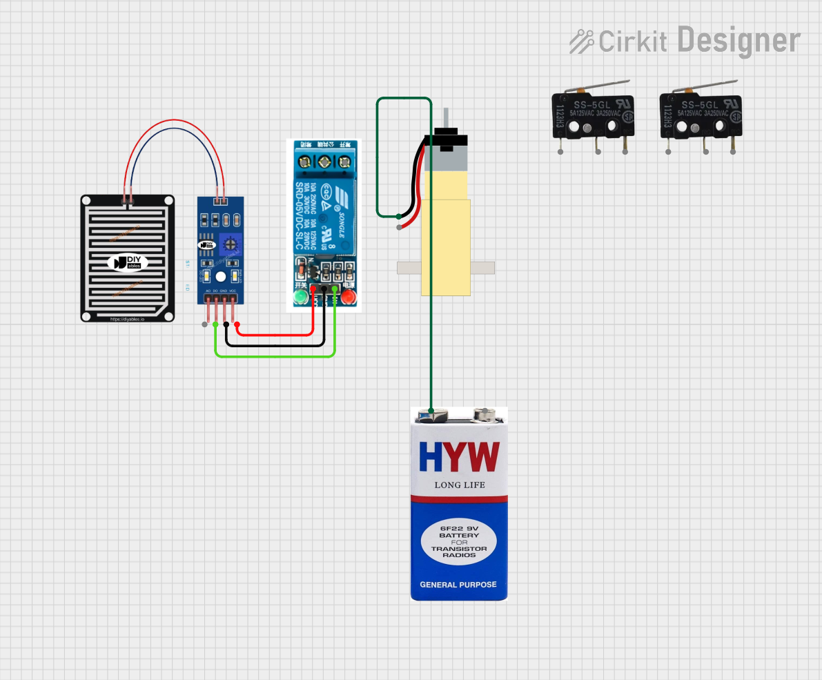
Circuit Documentation
Summary
This document provides a detailed overview of a circuit that includes a rain sensor, a 5V relay, a hobby gearmotor with a 48:1 gearbox, two micro switches, and a 9V battery. The circuit is designed to detect rain and activate a relay, which in turn controls the gearmotor. The micro switches are used for additional control or feedback mechanisms.
Component List
RAIN SENSOR
- Description: A sensor used to detect the presence of rain.
- Pins: AO, DO, GRD, VCC
5V Relay
- Description: An electromechanical switch used to control a high-power device with a low-power signal.
- Pins: Normally Open, Common terminal, Normally Closed, In, GND, VCC
Hobby Gearmotor with 48:1 Gearbox
- Description: A small motor with a gearbox that provides a 48:1 reduction ratio.
- Pins: pin 1, pin 2
Micro Switch (1)
- Description: A small switch used for control or feedback.
- Pins: COM, NO, NC
Micro Switch (2)
- Description: A small switch used for control or feedback.
- Pins: COM, NO, NC
9V Battery
- Description: A standard 9V battery used to power the circuit.
- Pins: +, -
Wiring Details
RAIN SENSOR
- DO is connected to In of the 5V Relay.
- GRD is connected to GND of the 5V Relay.
- VCC is connected to VCC of the 5V Relay.
5V Relay
- In is connected to DO of the Rain Sensor.
- GND is connected to GRD of the Rain Sensor.
- VCC is connected to VCC of the Rain Sensor.
Hobby Gearmotor with 48:1 Gearbox
- pin 1 is connected to + of the 9V Battery.
Micro Switch (1)
- COM is not connected in this circuit.
- NO is not connected in this circuit.
- NC is not connected in this circuit.
Micro Switch (2)
- COM is not connected in this circuit.
- NO is not connected in this circuit.
- NC is not connected in this circuit.
9V Battery
- + is connected to pin 1 of the Hobby Gearmotor with 48:1 Gearbox.
- - is not connected in this circuit.
Code
There is no microcontroller code provided for this circuit.
This document provides a comprehensive overview of the components and their interconnections in the circuit. Each component is described, and the wiring details are provided to ensure proper assembly and functionality.