
Circuit Documentation
Summary
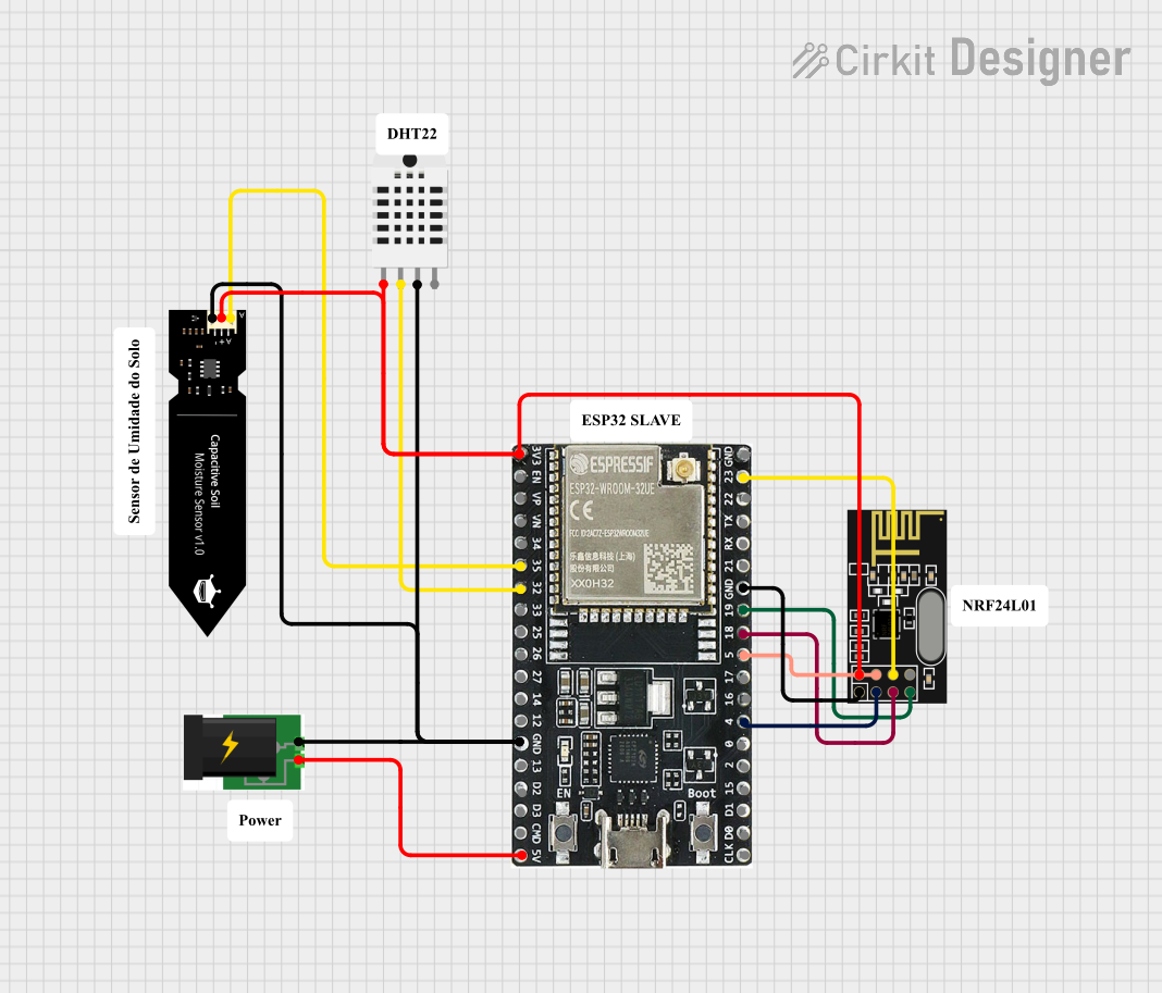
This document provides a detailed overview of a circuit that includes an ESP32 microcontroller, a humidity and temperature sensor (RHT03), an NRF24L01 wireless module, a capacitive soil moisture sensor, and a power supply. The circuit is designed to collect environmental data and transmit it wirelessly.
Component List
ESP32-WROOM-32UE
- Description: A powerful microcontroller with Wi-Fi and Bluetooth capabilities.
- Pins: 3v3, EN, VP, VN, 34, 35, 32, 33, 25, 26, 14, 12, GND, 13, D2, D3, 5V, 23, 22, TX, RX, 21, 19, 18, 5, 17, 16, 4, 0, 2, 15, D1, D0, CKL
Humidity and Temperature Sensor (RHT03)
- Description: A sensor used to measure humidity and temperature.
- Pins: Vcc, Data-signal, GND 1, GND 2
NRF24L01
- Description: A wireless transceiver module for communication.
- Pins: IRQ (not used), MOSI, CSN, VCC (3V), GND, CE, SCK, MISO
POWER
- Description: Power supply for the circuit.
- Pins: +, -
DFRobot Capacitive Soil Moisture Sensor (V1.0)
- Description: A sensor used to measure soil moisture levels.
- Pins: A, VCC, GND
Comment
- Description: Placeholder for comments in the circuit design.
- Pins: None
Wiring Details
ESP32-WROOM-32UE
3v3 is connected to:
- VCC (3V) of NRF24L01
- VCC of DFRobot Capacitive Soil Moisture Sensor (V1.0)
- Vcc of Humidity and Temperature Sensor (RHT03)
35 is connected to:
- A of DFRobot Capacitive Soil Moisture Sensor (V1.0)
32 is connected to:
- Data-signal of Humidity and Temperature Sensor (RHT03)
GND is connected to:
-
- of POWER
- GND of DFRobot Capacitive Soil Moisture Sensor (V1.0)
- GND 1 of Humidity and Temperature Sensor (RHT03)
- GND of NRF24L01
-
5V is connected to:
-
- of POWER
-
23 is connected to:
- MOSI of NRF24L01
19 is connected to:
- MISO of NRF24L01
18 is connected to:
- SCK of NRF24L01
5 is connected to:
- CSN of NRF24L01
4 is connected to:
- CE of NRF24L01
Humidity and Temperature Sensor (RHT03)
Vcc is connected to:
- 3v3 of ESP32-WROOM-32UE
Data-signal is connected to:
- 32 of ESP32-WROOM-32UE
GND 1 is connected to:
- GND of ESP32-WROOM-32UE
NRF24L01
VCC (3V) is connected to:
- 3v3 of ESP32-WROOM-32UE
MOSI is connected to:
- 23 of ESP32-WROOM-32UE
CSN is connected to:
- 5 of ESP32-WROOM-32UE
GND is connected to:
- GND of ESP32-WROOM-32UE
CE is connected to:
- 4 of ESP32-WROOM-32UE
SCK is connected to:
- 18 of ESP32-WROOM-32UE
MISO is connected to:
- 19 of ESP32-WROOM-32UE
POWER
+ is connected to:
- 5V of ESP32-WROOM-32UE
- is connected to:
- GND of ESP32-WROOM-32UE
DFRobot Capacitive Soil Moisture Sensor (V1.0)
VCC is connected to:
- 3v3 of ESP32-WROOM-32UE
A is connected to:
- 35 of ESP32-WROOM-32UE
GND is connected to:
- GND of ESP32-WROOM-32UE
Code
No code is provided for this circuit.