Arduino UNO-Based Water Quality Monitoring System with GSM SIM900
Water Quality and Temperature Monitoring System
Summary
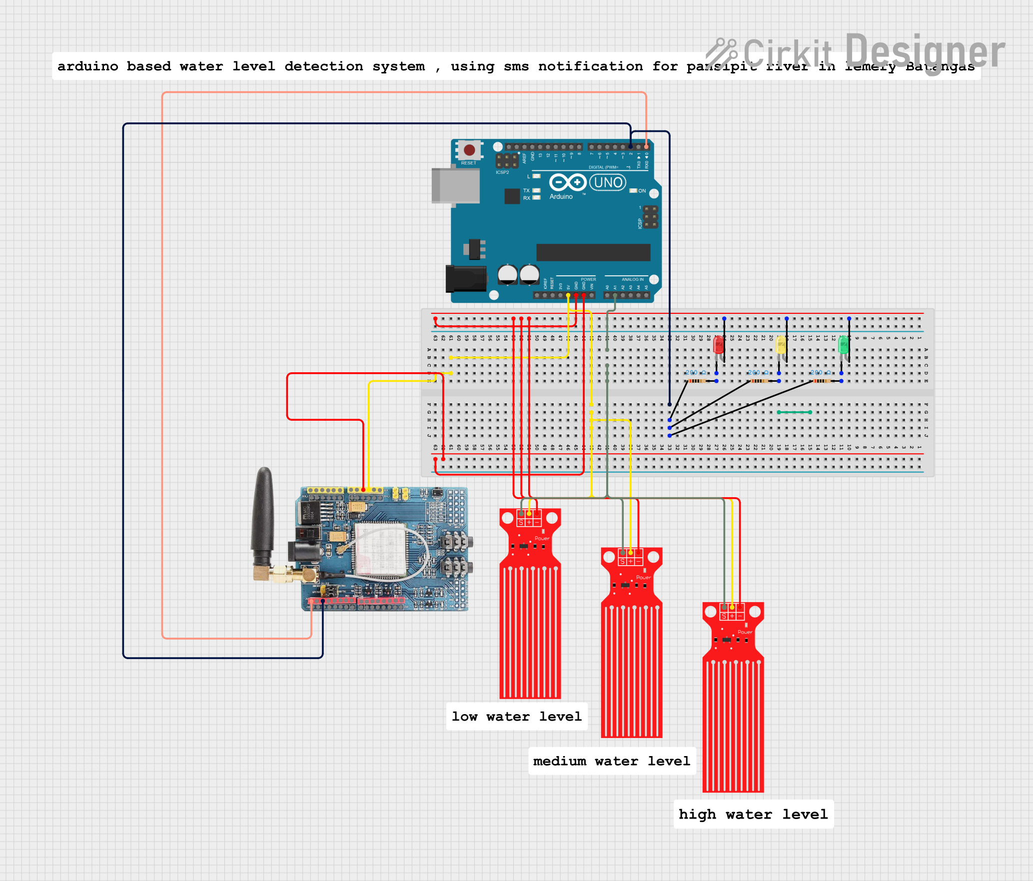
This circuit is designed to monitor water quality and temperature using an Arduino UNO, a GSM SIM900 module, multiple water level sensors, and LEDs. The system reads temperature data from a TEMP sensor and TDS data from a TDS sensor module, displays the data on a 16x2 I2C LCD, and sends the data via the GSM SIM900 module. The status is indicated using LEDs.
Component List
Arduino UNO
- Description: Microcontroller board based on the ATmega328P.
- Pins: UNUSED, IOREF, Reset, 3.3V, 5V, GND, Vin, A0, A1, A2, A3, A4, A5, SCL, SDA, AREF, D13, D12, D11, D10, D9, D8, D7, D6, D5, D4, D3, D2, D1, D0
GSM SIM900
- Description: GSM module for sending and receiving SMS.
- Pins: A5, A4, A3, A2, A1, A0, 5V, GND, 3.3V, RESET, D0, D1, D2, D3, D4, D5, D6, D7, D8, D9, D10, D11, D12, D13, AREF
Water Level Sensor
- Description: Sensor to detect water level.
- Pins: SIG, VCC, GND
LED: Two Pin (red)
- Description: Red LED for status indication.
- Pins: cathode, anode
LED: Two Pin (yellow)
- Description: Yellow LED for status indication.
- Pins: cathode, anode
LED: Two Pin (green)
- Description: Green LED for status indication.
- Pins: cathode, anode
Resistor (200 Ohms)
- Description: Resistor to limit current.
- Pins: pin1, pin2
Wiring Details
Arduino UNO
- D2: Connected to pin1 of three resistors and D2 of GSM SIM900.
- A1: Connected to SIG of three water level sensors.
- 5V: Connected to VCC of three water level sensors and 5V of GSM SIM900.
- GND: Connected to GND of three water level sensors, anode of three LEDs, and GND of GSM SIM900.
- D0: Connected to D0 of GSM SIM900.
GSM SIM900
- D2: Connected to D2 of Arduino UNO and pin1 of three resistors.
- 5V: Connected to 5V of Arduino UNO and VCC of three water level sensors.
- GND: Connected to GND of Arduino UNO and GND of three water level sensors.
- D0: Connected to D0 of Arduino UNO.
Water Level Sensor
- SIG: Connected to A1 of Arduino UNO.
- VCC: Connected to 5V of Arduino UNO and GSM SIM900.
- GND: Connected to GND of Arduino UNO and GSM SIM900.
LED: Two Pin (red)
- anode: Connected to GND of Arduino UNO.
- cathode: Connected to pin2 of a resistor.
LED: Two Pin (yellow)
- anode: Connected to GND of Arduino UNO.
- cathode: Connected to pin2 of a resistor.
LED: Two Pin (green)
- anode: Connected to GND of Arduino UNO.
- cathode: Connected to pin2 of a resistor.
Resistor (200 Ohms)
- pin1: Connected to D2 of Arduino UNO and GSM SIM900.
- pin2: Connected to cathode of an LED.
Code Documentation
/*
 * Water Quality and Temperature Monitoring System
 * This Arduino sketch reads temperature data from a TEMP sensor, TDS data from a
 * TDS Sensor Module, and displays the data on a 16x2 I2C LCD. It also sends the
 * data via a GSM SIM900 module and indicates status with an LED.
 */

#include <Wire.h>
#include <LiquidCrystal_I2C.h>

// LCD setup
LiquidCrystal_I2C lcd(0x27, 16, 2);

// Pin definitions
const int tempPin = 3; // TEMP sensor connected to D3
const int tdsPin = A0; // TDS sensor connected to A0
const int ledPin = 13; // LED connected to D13

void setup() {
  // Initialize serial communication
  Serial.begin(9600);

  // Initialize LCD
  lcd.begin();
  lcd.backlight();

  // Initialize TEMP sensor pin
  pinMode(tempPin, INPUT);

  // Initialize LED pin
  pinMode(ledPin, OUTPUT);

  // Initialize GSM module
  Serial1.begin(9600); // GSM module connected to D0 (RX) and D2 (TX)

  // Display startup message
  lcd.setCursor(0, 0);
  lcd.print("Water Quality");
  lcd.setCursor(0, 1);
  lcd.print("Monitoring");
  delay(2000);
  lcd.clear();
}

void loop() {
  // Read temperature data
  int tempValue = analogRead(tempPin);
  float temperature = (tempValue / 1024.0) * 5.0 * 100.0;

  // Read TDS data
  int tdsValue = analogRead(tdsPin);
  float tds = (tdsValue / 1024.0) * 5.0 * 1000.0;

  // Display data on LCD
  lcd.setCursor(0, 0);
  lcd.print("Temp: ");
  lcd.print(temperature);
  lcd.print(" C");
  lcd.setCursor(0, 1);
  lcd.print("TDS: ");
  lcd.print(tds);
  lcd.print(" ppm");

  // Send data via GSM module
  Serial1.print("AT+CMGF=1\r"); // Set SMS mode to text
  delay(1000);
  Serial1.print("AT+CMGS=\"+1234567890\"\r"); // Replace with your phone number
  delay(1000);
  Serial1.print("Temp: ");
  Serial1.print(temperature);
  Serial1.print(" C, TDS: ");
  Serial1.print(tds);
  Serial1.print(" ppm");
  delay(1000);
  Serial1.write(26); // ASCII code for CTRL+Z to send SMS
  delay(5000);

  // Indicate status with LED
  digitalWrite(ledPin, HIGH); // Turn on LED
  delay(500);
  digitalWrite(ledPin, LOW); // Turn off LED

  // Wait before next reading
  delay(10000);
}
This code initializes the necessary components, reads data from the sensors, displays the data on an LCD, sends the data via the GSM module, and indicates the status using an LED. The loop function continuously reads the sensor data, updates the display, sends the data, and toggles the LED status.