
ESP32-Based RFID Music Player with TFT Display and Push Button Control
View and Edit Project In Cirkit Designer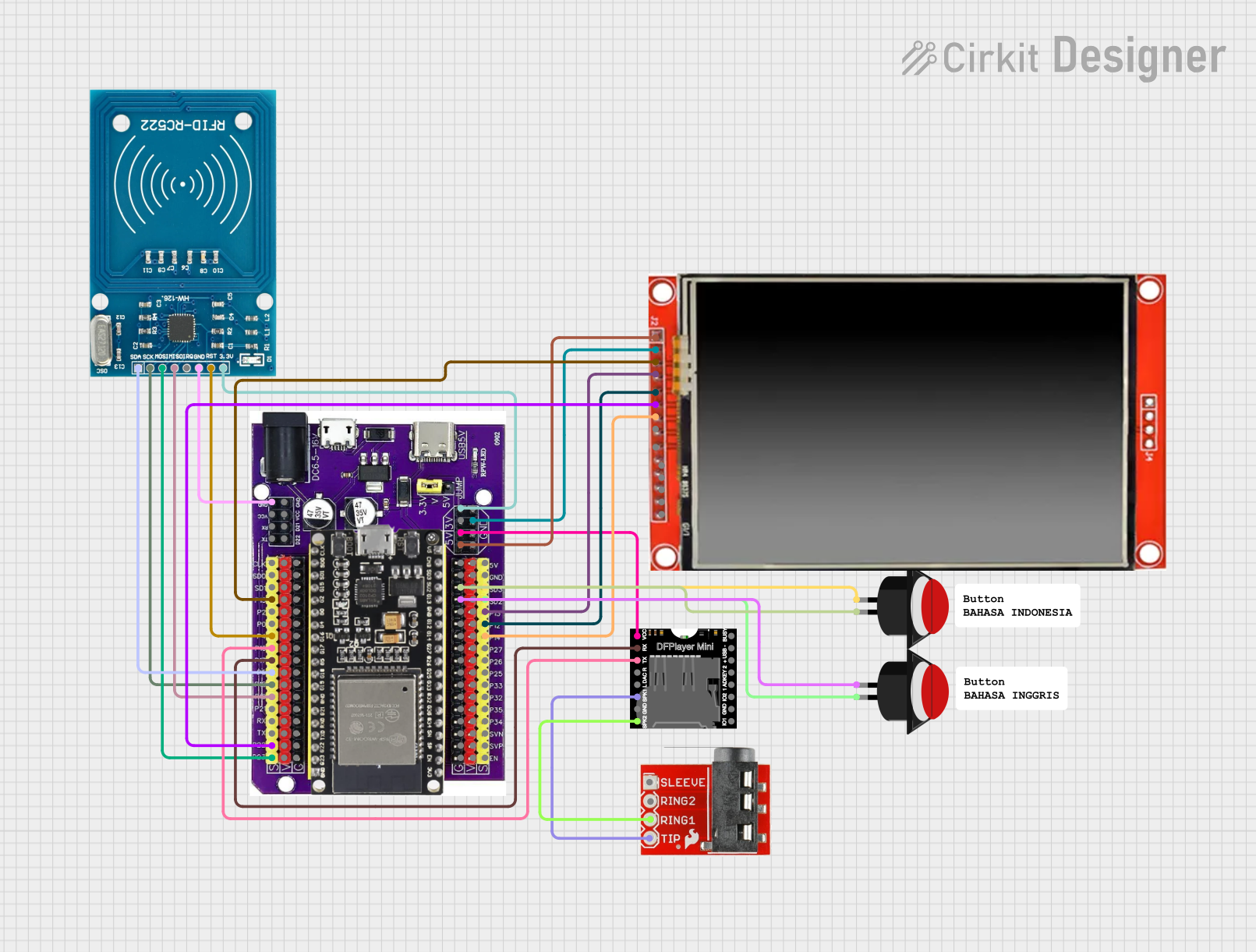
Circuit Documentation
Summary
This document provides a detailed overview of a circuit that includes an ESP32 microcontroller, an RFID reader, a DFPlayer Mini, an LCD TFT screen, push buttons, and a TRRS 3.5mm jack breakout. The circuit is designed to interface these components for various functionalities such as reading RFID tags, playing audio, and displaying information on an LCD screen.
Component List
Push Button Round
- Pins: leg0, leg1
- Description: A simple push button used for user input.
DFPlayer MINI
- Pins: VCC, BUSY, RX, USB -, TX, USB +, DAC_R, K2/ADC_KEY, DAC_L, K1/ADC_KEY, SPK1, IO 2, GND, SPK2, IO 1
- Description: A small MP3 player module that can be controlled via serial communication.
RFID-RC522
- Pins: VCC (3.3V), RST, GND, IRQ, MISO, MOSI, SCK, SDA
- Description: An RFID reader module used for reading RFID tags.
LCD TFT screen ILI9488 HD
- Pins: PEN, TDO, TDI, VCC (3.3~5V), GND, CS, RST, D/C, SDI(MOSI), SCK, BL, SDO(MISO), TCS, TCK
- Description: A high-definition LCD screen for displaying information.
Esp32 on Baseboard
- Pins: GPIO23, GPIO22, GPIO1/TX, GPIO3/RX, GPIO21, GPIO19, GPIO18, GPIO5, GPIO17, GPIO16, GPIO4, GPIO0, GPIO2, GPIO15, SD1, SD0, CLK, V, G, GPIO36, GPIO39, GPIO34, GPIO35, GPIO32, GPIO33, GPIO25, GPIO26, GPIO27, GPIO14, GPIO12, GPIO13, SD2, SD3, GND, 5V, 3V, TX, RX, VCC, D22, D21
- Description: A versatile microcontroller with Wi-Fi and Bluetooth capabilities.
TRRS 3.5mm Jack Breakout
- Pins: Sleeve, Ring2, Ring1, Tip
- Description: A breakout board for a 3.5mm audio jack.
Comment
- Pins: None
- Description: Used for adding comments in the circuit design.
Wiring Details
Push Button Round
Push Button 1:
- leg0 connected to Esp32 on Baseboard GPIO SD3
- leg1 connected to Esp32 on Baseboard G
Push Button 2:
- leg0 connected to Esp32 on Baseboard G
- leg1 connected to Esp32 on Baseboard GPIO SD2
DFPlayer MINI
- VCC connected to Esp32 on Baseboard 5V
- RX connected to Esp32 on Baseboard GPIO17
- TX connected to Esp32 on Baseboard GPIO16
- SPK1 connected to TRRS 3.5mm Jack Breakout Tip
- SPK2 connected to TRRS 3.5mm Jack Breakout Ring1
RFID-RC522
- VCC (3.3V) connected to Esp32 on Baseboard 3V
- RST connected to Esp32 on Baseboard GPIO4
- GND connected to Esp32 on Baseboard GND
- MISO connected to Esp32 on Baseboard GPIO19
- MOSI connected to Esp32 on Baseboard GPIO23
- SCK connected to Esp32 on Baseboard GPIO18
- SDA connected to Esp32 on Baseboard GPIO5
LCD TFT screen ILI9488 HD
- VCC (3.3~5V) connected to Esp32 on Baseboard 5V
- GND connected to Esp32 on Baseboard GND
- CS connected to Esp32 on Baseboard GPIO15
- RST connected to Esp32 on Baseboard GPIO13
- D/C connected to Esp32 on Baseboard GPIO12
- SDI(MOSI) connected to Esp32 on Baseboard GPIO22
- SCK connected to Esp32 on Baseboard GPIO14
Esp32 on Baseboard
- 3V connected to RFID-RC522 VCC (3.3V)
- GPIO4 connected to RFID-RC522 RST
- GND connected to RFID-RC522 GND
- GPIO19 connected to RFID-RC522 MISO
- GPIO23 connected to RFID-RC522 MOSI
- GPIO18 connected to RFID-RC522 SCK
- GPIO5 connected to RFID-RC522 SDA
- SD3 connected to Push Button Round leg0
- G connected to Push Button Round leg1
- G connected to Push Button Round leg0
- SD2 connected to Push Button Round leg1
- 5V connected to DFPlayer MINI VCC
- GPIO17 connected to DFPlayer MINI RX
- GPIO16 connected to DFPlayer MINI TX
- 5V connected to LCD TFT screen ILI9488 HD VCC (3.3~5V)
- GND connected to LCD TFT screen ILI9488 HD GND
- GPIO15 connected to LCD TFT screen ILI9488 HD CS
- GPIO13 connected to LCD TFT screen ILI9488 HD RST
- GPIO12 connected to LCD TFT screen ILI9488 HD D/C
- GPIO22 connected to LCD TFT screen ILI9488 HD SDI(MOSI)
- GPIO14 connected to LCD TFT screen ILI9488 HD SCK
TRRS 3.5mm Jack Breakout
- Tip connected to DFPlayer MINI SPK1
- Ring1 connected to DFPlayer MINI SPK2
Code
No code is provided for this circuit.
This document provides a comprehensive overview of the circuit, including a summary, component list, wiring details, and code documentation. Each section is designed to help understand the circuit's design and functionality.