Cirkit Designer
Your all-in-one circuit design IDE
Home /
Project Documentation
Arduino UNO Sound Level Meter with LED Indicators and LCD Display
Circuit Documentation
Summary
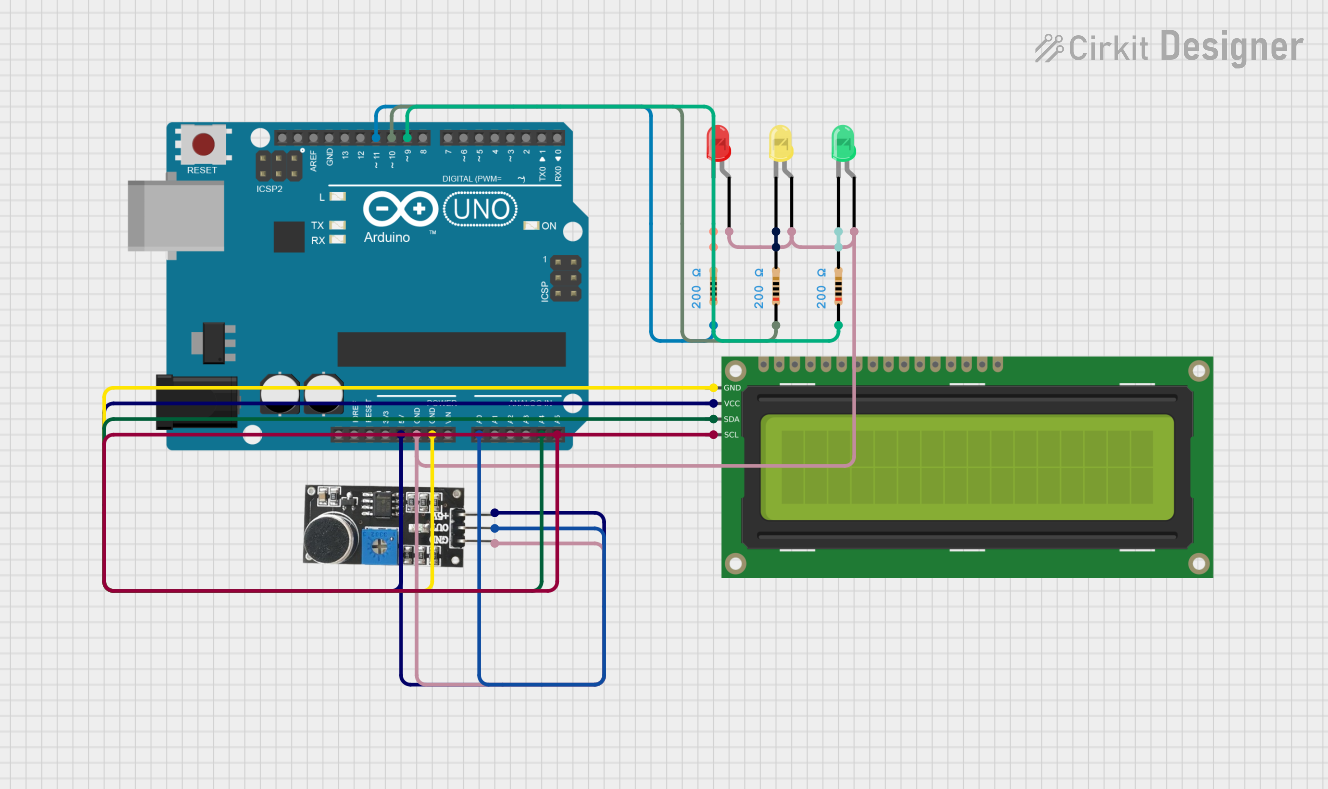
This circuit is designed to measure sound levels using a sound sensor and display the loudness in decibels (dB) on a 16x2 I2C LCD. Additionally, it uses three LEDs (red, green, and yellow) to indicate different sound levels: Quiet, Moderate, and Loud. The circuit is controlled by an Arduino UNO microcontroller.
Component List
Arduino UNO
- Description: Microcontroller board based on the ATmega328P.
- Pins: UNUSED, IOREF, Reset, 3.3V, 5V, GND, Vin, A0, A1, A2, A3, A4, A5, SCL, SDA, AREF, D13, D12, D11, D10, D9, D8, D7, D6, D5, D4, D3, D2, D1, D0
LED: Two Pin (red)
- Description: Red LED with two pins (anode and cathode).
- Pins: cathode, anode
LED: Two Pin (green)
- Description: Green LED with two pins (anode and cathode).
- Pins: cathode, anode
LED: Two Pin (yellow)
- Description: Yellow LED with two pins (anode and cathode).
- Pins: cathode, anode
Resistor (200 Ohms)
- Description: Resistor with a resistance of 200 Ohms.
- Pins: pin1, pin2
16x2 I2C LCD
- Description: 16x2 character LCD with I2C interface.
- Pins: GND, VCC, SDA, SCL
Sound Sensor
- Description: Sensor to detect sound levels.
- Pins: 5V +, OUT, GND
Wiring Details
Arduino UNO
- 5V: Connected to VCC of 16x2 I2C LCD and 5V + of Sound Sensor.
- GND: Connected to GND of 16x2 I2C LCD, GND of Sound Sensor, and anodes of all LEDs.
- A0: Connected to OUT of Sound Sensor.
- A4: Connected to SDA of 16x2 I2C LCD.
- A5: Connected to SCL of 16x2 I2C LCD.
- D11: Connected to pin1 of a 200 Ohm Resistor (for Quiet level).
- D10: Connected to pin1 of a 200 Ohm Resistor (for Moderate level).
- D9: Connected to pin1 of a 200 Ohm Resistor (for Loud level).
LED: Two Pin (red)
- anode: Connected to GND of Sound Sensor and Arduino UNO.
- cathode: Connected to pin2 of a 200 Ohm Resistor (for Quiet level).
LED: Two Pin (green)
- anode: Connected to GND of Sound Sensor and Arduino UNO.
- cathode: Connected to pin2 of a 200 Ohm Resistor (for Loud level).
LED: Two Pin (yellow)
- anode: Connected to GND of Sound Sensor and Arduino UNO.
- cathode: Connected to pin2 of a 200 Ohm Resistor (for Moderate level).
Resistor (200 Ohms)
- pin1: Connected to D11, D10, and D9 of Arduino UNO.
- pin2: Connected to cathodes of red, yellow, and green LEDs respectively.
16x2 I2C LCD
- VCC: Connected to 5V of Arduino UNO.
- GND: Connected to GND of Arduino UNO.
- SDA: Connected to A4 of Arduino UNO.
- SCL: Connected to A5 of Arduino UNO.
Sound Sensor
- 5V +: Connected to 5V of Arduino UNO.
- OUT: Connected to A0 of Arduino UNO.
- GND: Connected to GND of Arduino UNO and anodes of all LEDs.
Documented Code
#include <Wire.h>
#include <LiquidCrystal_I2C.h> // Library for the LCD screen

// Create an instance of the LCD with the address 0x27 and 16x2 dimensions
LiquidCrystal_I2C lcd(0x3F, 16, 2);

const int SENSOR_PIN = A0; // Pin for the sound sensor (Analog pin A0)
const int PIN_QUIET = 11; // Pin for "Quiet" level output
const int PIN_MODERATE = 10; // Pin for "Moderate" level output
const int PIN_LOUD = 9; // Pin for "Loud" level output

const int sampleWindow = 50; // Sample window size in milliseconds (50 ms = 20 Hz)
unsigned int sample;

void setup() {
  lcd.init(); // Initialize the LCD screen
  pinMode(SENSOR_PIN, INPUT); // Set the sound sensor pin as an input
  pinMode(PIN_QUIET, OUTPUT); // Set the pins for sound level indicators as output
  pinMode(PIN_MODERATE, OUTPUT);
  pinMode(PIN_LOUD, OUTPUT);

  // Set the sound level output pins to LOW initially
  digitalWrite(PIN_QUIET, LOW);
  digitalWrite(PIN_MODERATE, LOW);
  digitalWrite(PIN_LOUD, LOW);

  Serial.begin(9600); // Initialize serial communication for debugging
  lcd.backlight(); // Turn on the LCD backlight
}

void loop() {
  lcd.clear(); // Clear the LCD screen

  unsigned long startMillis = millis(); // Start timing for the sample window
  float peakToPeak = 0; // Variable to store the peak-to-peak value
  unsigned int signalMax = 0; // Maximum signal value during the window
  unsigned int signalMin = 1024; // Minimum signal value during the window

  // Collect data for the duration of the sample window (50 ms)
  while (millis() - startMillis < sampleWindow) {
    sample = analogRead(SENSOR_PIN); // Read the value from the sound sensor

    // Filter out invalid values
    if (sample < 1024) {
      if (sample > signalMax) {
        signalMax = sample; // Update the maximum value
      } else if (sample < signalMin) {
        signalMin = sample; // Update the minimum value
      }
    }
  }

  peakToPeak = signalMax - signalMin; // Calculate the peak-to-peak amplitude
  int db = map(peakToPeak, 20, 750, 49.5, 90); // Map the amplitude to decibels (dB)

  // Display the loudness in decibels on the LCD
  lcd.setCursor(0, 0);
  lcd.print("Loudness: ");
  lcd.print(db);
  lcd.print(" dB");

  // Set the output level based on the dB value
  if (db <= 60) {
    lcd.setCursor(0, 1);
    lcd.print("Level: Quiet");
    digitalWrite(PIN_QUIET, HIGH); // Activate Quiet level
    digitalWrite(PIN_MODERATE, LOW); // Deactivate Moderate level
    digitalWrite(PIN_LOUD, LOW); // Deactivate Loud level
  } else if (db > 60 && db < 85) {
    lcd.setCursor(0, 1);
    lcd.print("Level: Moderate");
    digitalWrite(PIN_QUIET, LOW); // Deactivate Quiet level
    digitalWrite(PIN_MODERATE, HIGH); // Activate Moderate level
    digitalWrite(PIN_LOUD, LOW); // Deactivate Loud level
  } else if (db >= 85) {
    lcd.setCursor(0, 1);
    lcd.print("Level: High");
    digitalWrite(PIN_QUIET, LOW); // Deactivate Quiet level
    digitalWrite(PIN_MODERATE, LOW); // Deactivate Moderate level
    digitalWrite(PIN_LOUD, HIGH); // Activate Loud level
  }

  delay(1500); // Wait for 1.5 seconds before the next reading
}
This code initializes the LCD and sets up the pins for the sound sensor and LEDs. It continuously reads the sound level, calculates the peak-to-peak amplitude, maps it to decibels, and displays the loudness on the LCD. Based on the dB value, it activates the corresponding LED to indicate the sound level.