Arduino Nano Controlled OLED Display with Push Button Interface
Circuit Documentation
Summary of the Circuit
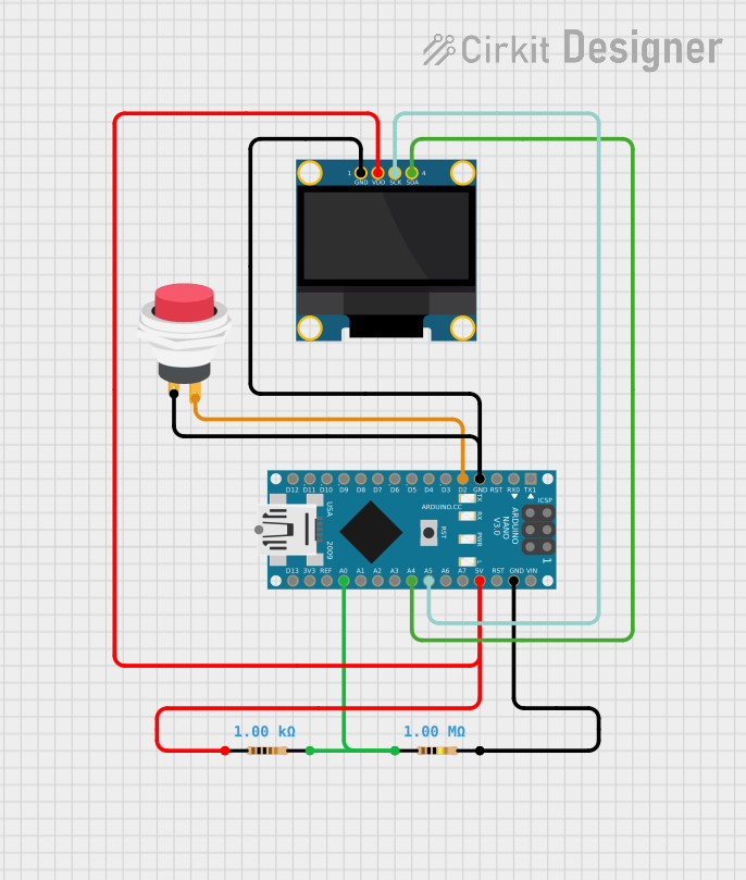
This circuit appears to be designed to interface an Arduino Nano with an OLED 128x64 I2C Monochrome Display and includes a push switch and two resistors of different values. The Arduino Nano is used as the central microcontroller unit to control the OLED display and read the state of the push switch. The resistors may be used for pull-up/pull-down configurations or current limiting purposes.
Component List
Resistor 1
- Component Name: Resistor
- Resistance: 1000 Ohms
- Description: A resistor with a resistance of 1k Ohm, typically used for current limiting or voltage division.
Resistor 2
- Component Name: Resistor
- Resistance: 1000000 Ohms
- Description: A resistor with a resistance of 1M Ohm, possibly used as a pull-up or pull-down resistor.
Arduino Nano
- Component Name: Arduino Nano
- Description: A compact microcontroller board based on the ATmega328P, equipped with a variety of digital and analog pins.
2Pin Push Switch
- Component Name: 2Pin Push Switch
- Description: A momentary push switch that can be used to trigger events or interrupt signals in the circuit.
OLED 128x64 I2C Monochrome Display
- Component Name: OLED 128x64 I2C Monochrome Display GND-VDD
- Description: A small graphical display that uses the I2C protocol for communication, capable of displaying monochrome graphics and text.
Wiring Details
Resistor 1
- Connected to Arduino Nano 5V: Provides power to the circuit.
- Connected to OLED Display VDD: Limits the current to the display or acts as a pull-up resistor.
Resistor 2
- Connected to Arduino Nano A0: May be part of a voltage divider or sensor interface.
- Connected to Arduino Nano GND: Completes the circuit for the voltage divider or sensor interface.
Arduino Nano
- 5V: Powers the OLED display through Resistor 1.
- A0: Connected to Resistor 2 for analog input.
- GND: Common ground for the circuit.
- D2: Connected to the output of the push switch.
- A5 (SCK): I2C clock line for the OLED display.
- A4 (SDA): I2C data line for the OLED display.
2Pin Push Switch
- Input +: Connected to Arduino Nano GND.
- Output +: Connected to Arduino Nano D2.
OLED 128x64 I2C Monochrome Display
- GND: Common ground with Arduino Nano.
- VDD: Powered through Resistor 1 from Arduino Nano 5V.
- SCK: I2C clock line connected to Arduino Nano A5.
- SDA: I2C data line connected to Arduino Nano A4.
Documented Code
Arduino Nano Code (sketch.ino)
void setup() {
  // put your setup code here, to run once:

}

void loop() {
  // put your main code here, to run repeatedly:

}
This code template is the default for an Arduino sketch. The setup() function is intended to contain initialization code that runs once, such as pin mode configurations. The loop() function is meant to contain the main logic of the program, which runs repeatedly after setup() is complete. The actual functionality needs to be implemented by the user based on the specific requirements of the circuit.
Additional Notes
- The provided code does not include any specific functionality and needs to be populated with the logic to interact with the OLED display and read the state of the push switch.
- The I2C communication setup and any libraries required for the OLED display are not included and should be added to the
setup()function. - The push switch state can be read in the
loop()function to trigger events or updates to the display.