T-Display S3 and HX711-Based Load Cell Measurement System with Audio Alert
Circuit Documentation
Summary
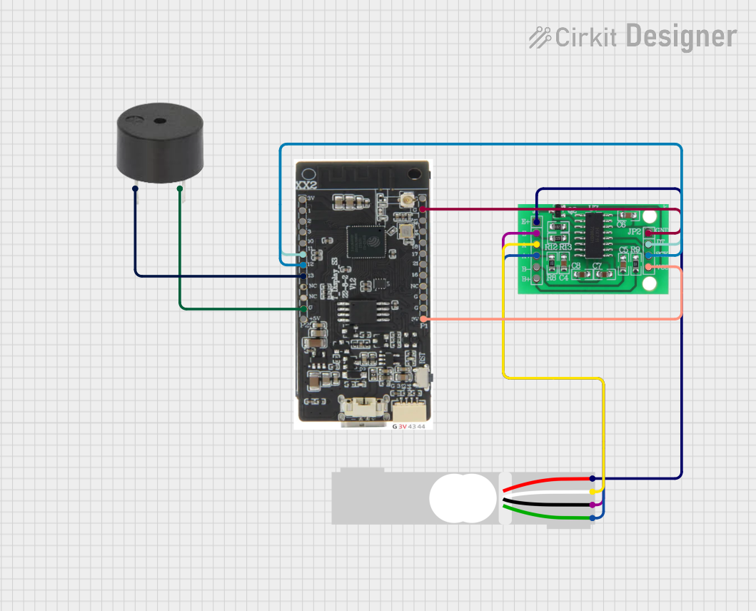
The circuit in question is designed to interface a load cell with a microcontroller unit (MCU) for weight measurement, and provide visual feedback through a display as well as auditory feedback using a buzzer. The MCU used in this circuit is the T-Display-S3, which is responsible for processing the data from the load cell through the HX711 bridge sensor interface. The HX711 acts as an analog-to-digital converter, amplifying the signals from the load cell. The buzzer is controlled by the MCU to provide an alert or feedback based on certain conditions or thresholds.
Component List
T-Display-S3
- Description: A microcontroller unit with an integrated display, capable of driving various peripherals and interfacing with sensors.
- Pins: 3V, 1, 2, 3, 10, 11, 12, 13, GND, 5V, 43, 44, 18, 17, 21, 16
HX711 - Bridge Sensor Interface
- Description: A precision 24-bit analog-to-digital converter (ADC) designed for weigh scales and industrial control applications to interface directly with a bridge sensor.
- Pins: E+, E-, A-, A+, B-, B+, GND - GROUND, DATA (OUT), SCK - CLOCK (IN), 3.3/3.5V Supply
Load Cell - Red/white/black/green
- Description: A transducer that converts force into an electrical signal, used in this circuit for weight measurement.
- Pins: E+, A-, E-, A+
Buzzer
- Description: An electromechanical component that produces sound, used for auditory signaling in the circuit.
- Pins: PIN, GND
Wiring Details
T-Display-S3
- 3V connected to HX711 3.3/3.5V Supply
- 11 connected to HX711 DATA (OUT)
- 12 connected to HX711 SCK - CLOCK (IN)
- 13 connected to Buzzer PIN
- GND connected to Buzzer GND and HX711 GND - GROUND
HX711 - Bridge Sensor Interface
- E+ connected to Load Cell E+
- E- connected to Load Cell E-
- A- connected to Load Cell A-
- A+ connected to Load Cell A+
- DATA (OUT) connected to T-Display-S3 pin 11
- SCK - CLOCK (IN) connected to T-Display-S3 pin 12
- GND - GROUND connected to T-Display-S3 GND
- 3.3/3.5V Supply connected to T-Display-S3 3V
Load Cell - Red/white/black/green
- E+ connected to HX711 E+
- A- connected to HX711 A-
- E- connected to HX711 E-
- A+ connected to HX711 A+
Buzzer
- PIN connected to T-Display-S3 pin 13
- GND connected to T-Display-S3 GND
Documented Code
No code has been provided for the microcontroller. The documentation of the code would typically include a description of the functionality, setup, and main loop, along with any interrupt service routines or additional functions. Since no code is available, this section cannot be completed. If code becomes available, it should be documented here with comments explaining the purpose and functionality of each section of the code.