Cirkit Designer
Your all-in-one circuit design IDE
Home /
Project Documentation
ESP32 and L298N Motor Driver-Based Wi-Fi Controlled Robotic Car with Ultrasonic Sensor
Circuit Documentation
Summary
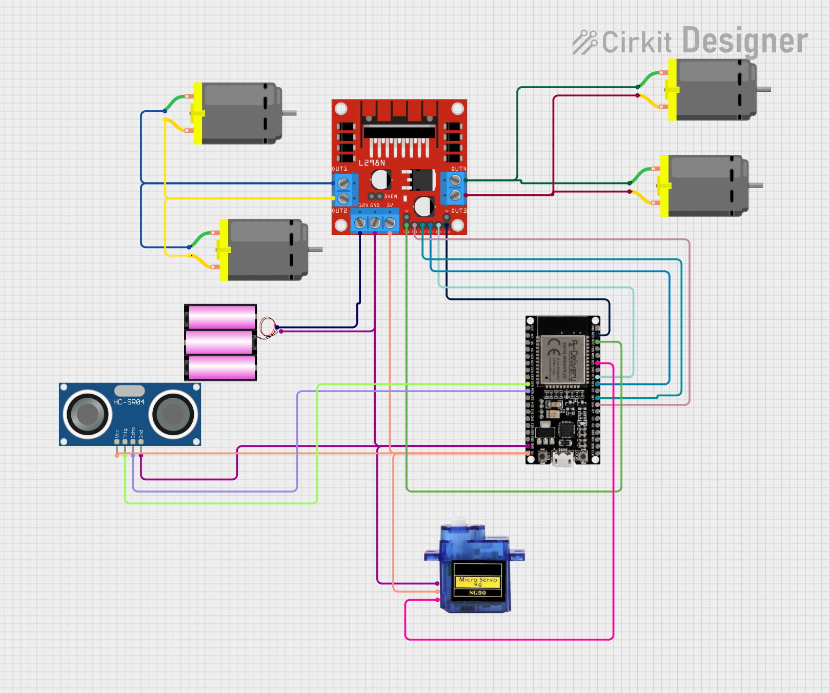
This document provides a detailed overview of a circuit that includes an L298N DC motor driver, multiple DC motors, a micro servo, an HC-SR04 ultrasonic sensor, an ESP32 microcontroller, and a 12V battery. The circuit is designed to control the motors and servo using the ESP32, with additional functionality provided by the ultrasonic sensor for distance measurement.
Component List
L298N DC Motor Driver
- Description: Dual H-Bridge motor driver
- Pins: OUT1, OUT2, 12V, GND, 5V, OUT3, OUT4, 5V-ENA-JMP-I, 5V-ENA-JMP-O, +5V-J1, +5V-J2, ENA, IN1, IN2, IN3, IN4, ENB
Micro Servo 9G
- Description: Small servo motor
- Pins: GND, +5V, PWM
HC-SR04 Ultrasonic Sensor
- Description: Ultrasonic distance sensor
- Pins: VCC, TRIG, ECHO, GND
DC Motor
- Description: Standard DC motor
- Pins: pin 1, pin 2
Battery 12V
- Description: 12V power source
- Pins: +, -
ESP32 38 PINS
- Description: Microcontroller with Wi-Fi and Bluetooth capabilities
- Pins: GND, G23, G22, TXD, RXD, G21, G19, G18, G5, G17, G16, G4, G0, G2, G15, SDI, SD0, CLK, 3V3, EN, SP, SN, G34, G35, G32, 33, G25, G26, G27, G14, G12, G13, SD2, SD3, 5V
Wiring Details
L298N DC Motor Driver
- OUT1: Connected to pin 1 of two DC Motors
- OUT2: Connected to pin 2 of two DC Motors
- OUT3: Connected to pin 2 of two DC Motors
- OUT4: Connected to pin 1 of two DC Motors
- 12V: Connected to the positive terminal of the 12V battery
- GND: Connected to the negative terminal of the 12V battery, GND of ESP32, GND of Micro Servo, and GND of HC-SR04
- 5V: Connected to 5V of ESP32, +5V of Micro Servo, and VCC of HC-SR04
- ENA: Connected to G22 of ESP32
- IN1: Connected to G16 of ESP32
- IN2: Connected to G17 of ESP32
- IN3: Connected to G18 of ESP32
- IN4: Connected to G19 of ESP32
- ENB: Connected to G23 of ESP32
Micro Servo 9G
- GND: Connected to GND of ESP32, GND of L298N, and GND of HC-SR04
- +5V: Connected to 5V of ESP32 and 5V of L298N
- PWM: Connected to G21 of ESP32
HC-SR04 Ultrasonic Sensor
- VCC: Connected to 5V of ESP32 and 5V of L298N
- TRIG: Connected to G25 of ESP32
- ECHO: Connected to G26 of ESP32
- GND: Connected to GND of ESP32, GND of L298N, and GND of Micro Servo
DC Motors
Motor 1 (Instance 1)
- pin 1: Connected to OUT1 of L298N
- pin 2: Connected to OUT2 of L298N
Motor 2 (Instance 2)
- pin 1: Connected to OUT1 of L298N
- pin 2: Connected to OUT2 of L298N
Motor 3 (Instance 3)
- pin 1: Connected to OUT4 of L298N
- pin 2: Connected to OUT3 of L298N
Motor 4 (Instance 4)
- pin 1: Connected to OUT4 of L298N
- pin 2: Connected to OUT3 of L298N
Battery 12V
- +: Connected to 12V of L298N
- -: Connected to GND of L298N, GND of ESP32, GND of Micro Servo, and GND of HC-SR04
ESP32 38 PINS
- GND: Connected to GND of L298N, GND of Micro Servo, and GND of HC-SR04
- 5V: Connected to 5V of L298N, +5V of Micro Servo, and VCC of HC-SR04
- G22: Connected to ENA of L298N
- G16: Connected to IN1 of L298N
- G17: Connected to IN2 of L298N
- G18: Connected to IN3 of L298N
- G19: Connected to IN4 of L298N
- G23: Connected to ENB of L298N
- G21: Connected to PWM of Micro Servo
- G25: Connected to TRIG of HC-SR04
- G26: Connected to ECHO of HC-SR04
Code
No code provided for this circuit.