Arduino Uno R3 Controlled Robotic Vehicle with Sensors and Actuators
Circuit Documentation
Summary
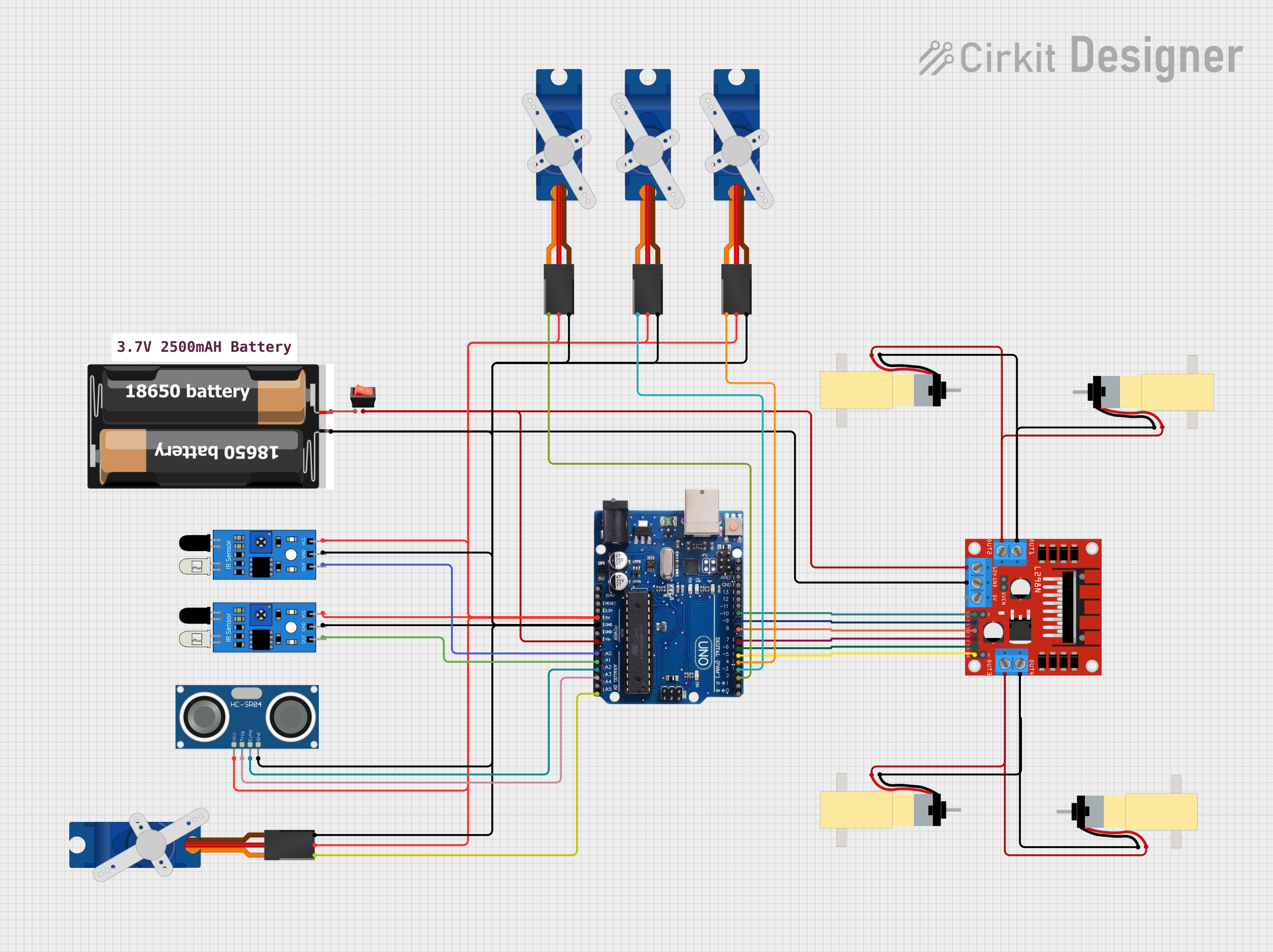
This circuit is designed to interface various sensors, actuators, and a motor driver with an Arduino Uno R3 microcontroller. The circuit includes IR sensors for object detection, an HC-SR04 ultrasonic sensor for distance measurement, SG90 servos for actuation, and a set of hobby gearmotors controlled by an L298N motor driver. A rocker switch is used to control power to the motor driver, and a 2x 18650 battery pack provides the power source. The circuit is likely intended for a small robot or an automated system that requires sensing and actuation capabilities.
Component List
Arduino Uno R3
- Microcontroller board based on the ATmega328P
- Features digital I/O pins, analog input pins, and various power pins
2x 18650 Battery Pack
- Provides power to the circuit
- Consists of two 18650 lithium-ion rechargeable batteries
Rocker Switch
- Used to control the power flow to the motor driver
- Has input and output pins for switching
L298N DC Motor Driver
- Used to control the speed and direction of DC motors
- Features inputs for motor control signals and outputs for motor connections
IR Sensors
- Used for object detection or line tracking
- Each sensor has an output, ground, and VCC pin
HC-SR04 Ultrasonic Sensor
- Measures distances using ultrasonic waves
- Has VCC, TRIG, ECHO, and GND pins
Tower Pro SG90 Servos
- Small servos used for precise angular movement
- Each servo has a signal, power (+5V), and ground (GND) pin
Hobby Gearmotors with 48:1 Gearbox
- DC motors with attached gearboxes for increased torque
- Each motor has two pins for electrical connection
Comment
- A placeholder for additional notes or comments about the circuit
Wiring Details
Arduino Uno R3
5Vconnected to various components for powerGNDconnected to various components for common groundVINconnected to the output of the rocker switch for motor driver powerA0connected to the output of one IR sensorA1connected to the output of another IR sensorA2connected to the ECHO pin of the HC-SR04 ultrasonic sensorA3connected to the TRIG pin of the HC-SR04 ultrasonic sensorA5/SCLconnected to the signal pin of one SG90 servo- Digital pins
2to10connected to signal pins of servos and control pins of the L298N motor driver
2x 18650 Battery Pack
vccconnected to the input of the rocker switchgndconnected to the common ground net
Rocker Switch
inputconnected to the VCC of the 2x 18650 battery packoutputconnected to the12Vpin of the L298N motor driver andVINof the Arduino Uno R3
L298N DC Motor Driver
12Vconnected to the output of the rocker switchGNDconnected to the common ground netENA,ENB,IN1,IN2,IN3,IN4connected to various digital pins on the Arduino Uno R3 for motor controlOUT1,OUT2,OUT3,OUT4connected to the pins of the hobby gearmotors
IR Sensors
vccconnected to the5Vpin of the Arduino Uno R3gndconnected to the common ground netoutconnected to theA0andA1pins of the Arduino Uno R3
HC-SR04 Ultrasonic Sensor
VCCconnected to the5Vpin of the Arduino Uno R3GNDconnected to the common ground netECHOconnected to theA2pin of the Arduino Uno R3TRIGconnected to theA3pin of the Arduino Uno R3
Tower Pro SG90 Servos
Signalconnected to various digital pins on the Arduino Uno R3+5Vconnected to the5Vpin of the Arduino Uno R3GNDconnected to the common ground net
Hobby Gearmotors with 48:1 Gearbox
pin 1andpin 2of each motor connected to the correspondingOUTpins of the L298N motor driver
Documented Code
No code has been provided for the microcontroller. The documentation of the code would typically include descriptions of the functionality implemented for each pin, initialization routines, main control loops, interrupt service routines, and any libraries used for interfacing with the components. Since no code is available, this section cannot be completed.