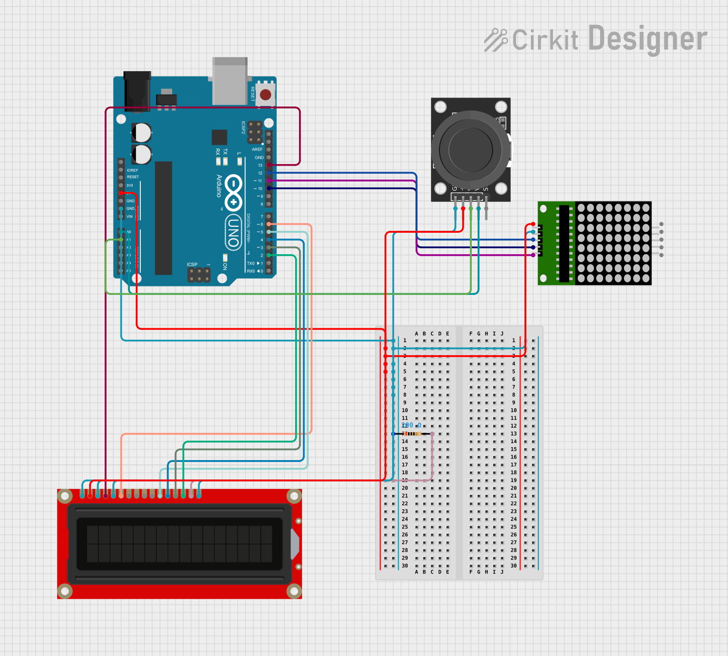
Arduino UNO Controlled LED Matrix and LCD Interface with Joystick Interaction

Circuit Documentation
Summary
This circuit integrates an 8x8 LED matrix, an Arduino UNO microcontroller, an LCD screen, a resistor, and a KY-023 Dual Axis Joystick Module to form a complex interactive system. The Arduino UNO serves as the central processing unit, controlling the LED matrix and LCD screen while receiving input from the joystick module. The resistor is used to limit current, possibly for backlight control on the LCD screen. The circuit is designed to be powered by a 5V supply from the Arduino UNO, which is distributed to the other components.
Component List
8x8 LED Matrix
- Description: A matrix of 64 LEDs arranged in an 8x8 grid.
- Pins: vcc, DIN, clk, CS, Gnd, gnd, CLK
Arduino UNO
- Description: A microcontroller board based on the ATmega328P.
- Pins: UNUSED, IOREF, Reset, 3.3V, 5V, GND, Vin, A0, A1, A2, A3, A4, A5, SCL, SDA, AREF, D13, D12, D11, D10, D9, D8, D7, D6, D5, D4, D3, D2, D1, D0
LCD Screen
- Description: A liquid crystal display for showing text and simple graphics.
- Pins: Backlight (GND), VSS, VDD, Contrast, RS, E, R/W, D0, D1, D2, D3, D4, D5, D6, D7, Backlight_PWR
Resistor
- Description: A passive two-terminal electrical component that implements electrical resistance as a circuit element.
- Pins: pin1, pin2
- Properties: Resistance: 200 Ohms
KY-023 Dual Axis Joystick Module
- Description: A module that provides two axes of analog input and a pushbutton.
- Pins: GND, +5V, VRx, VRy, SW
Wiring Details
8x8 LED Matrix
- vcc: Connected to 5V from Arduino UNO
- DIN: Connected to D12 on Arduino UNO
- clk: Connected to D10 on Arduino UNO
- CS: Connected to D11 on Arduino UNO
- Gnd: Connected to GND through a 200 Ohm resistor
Arduino UNO
- 5V: Provides power to the 8x8 LED matrix, LCD screen, and KY-023 Joystick Module
- GND: Common ground for the circuit
- D12: Connected to DIN on the 8x8 LED matrix
- D10: Connected to clk on the 8x8 LED matrix
- D11: Connected to CS on the 8x8 LED matrix
- A0: Connected to VRy on the KY-023 Joystick Module
- A1: Connected to VRx on the KY-023 Joystick Module
- D13: Connected to RS on the LCD screen
- D6: Connected to E on the LCD screen
- D5: Connected to D4 on the LCD screen
- D4: Connected to D5 on the LCD screen
- D3: Connected to D6 on the LCD screen
- D2: Connected to D7 on the LCD screen
LCD Screen
- VDD: Connected to 5V from Arduino UNO
- RS: Connected to D13 on Arduino UNO
- E: Connected to D6 on Arduino UNO
- R/W, VSS, Contrast, Backlight (GND): Connected to GND
- D4: Connected to D5 on Arduino UNO
- D5: Connected to D4 on Arduino UNO
- D6: Connected to D3 on Arduino UNO
- D7: Connected to D2 on Arduino UNO
- Backlight_PWR: Connected to pin2 of the resistor
Resistor
- pin1: Connected to Gnd of the 8x8 LED matrix
- pin2: Connected to Backlight_PWR on the LCD screen
KY-023 Dual Axis Joystick Module
- +5V: Connected to 5V from Arduino UNO
- GND: Connected to common ground
- VRx: Connected to A1 on Arduino UNO
- VRy: Connected to A0 on Arduino UNO
Documented Code
Arduino UNO Code (sketch.ino)
void setup() {
  // put your setup code here, to run once:

}

void loop() {
  // put your main code here, to run repeatedly:

}
Note: The provided code is a template and does not include specific functionality. It needs to be filled in with the logic to control the 8x8 LED matrix, read the joystick input, and update the LCD screen accordingly.