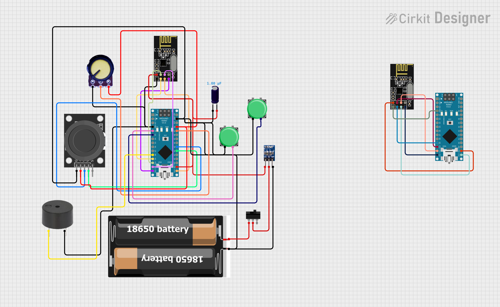
Arduino Nano-Based Drone Remote Control with NRF24L01 Wireless Communication

Circuit Documentation
Summary
This circuit is designed to interface an Arduino Nano with various peripherals including an NRF24L01 wireless transceiver module, a pushbutton, a potentiometer, a dual-axis joystick module, a toggle switch, a power supply consisting of two 18650 batteries, an AMS1117 3.3V voltage regulator, and a buzzer. The circuit is intended for wireless communication and control applications, with input devices for user interaction and a buzzer for audio feedback.
Component List
- Arduino Nano: A compact microcontroller board based on the ATmega328P, featuring digital and analog I/O pins.
- NRF24L01: A 2.4GHz wireless transceiver module for remote communication.
- Pushbutton: A momentary switch that can be used to trigger events or actions.
- Potentiometer: A three-terminal resistor with an adjustable center tap, providing variable voltage output.
- KY-023 Dual Axis Joystick Module: A joystick providing two analog outputs and one digital output to represent the X and Y positions.
- Toggle Switch: A switch that can maintain its state either in on or off positions.
- 2x 18650 Battery Pack: A power source for the circuit.
- AMS1117 3.3V: A voltage regulator that outputs a stable 3.3V from a higher voltage input.
- Electrolytic Capacitor: A capacitor used for filtering and stabilizing the voltage supply.
- Buzzer: An audio signaling device that can produce a tone when powered.
Wiring Details
Arduino Nano
- Digital Pins:
- D2, D3: Connected to Pushbuttons.
- D8: Connected to Buzzer.
- D9, D10: Connected to NRF24L01 CE and CSN pins respectively.
- D11/MOSI, D12/MISO, D13/SCK: Connected to NRF24L01 SPI interface pins.
- Analog Pins:
- A0-A7: Connected to Potentiometer and KY-023 Joystick Module.
- Power Pins:
- 5V: Connected to Potentiometer, Joystick Module, and AMS1117 3.3V IN.
- 3V3: Connected to NRF24L01 VCC.
- GND: Common ground for all components.
NRF24L01
- SPI Interface: Connected to corresponding SPI pins on Arduino Nano (D11/MOSI, D12/MISO, D13/SCK).
- Control Pins: CE connected to D9 and CSN connected to D10 on Arduino Nano.
- Power Pins: VCC connected to 3V3 and GND to common ground on Arduino Nano.
Pushbutton
- One side connected to Arduino Nano digital pins (D2, D3) and the other side to ground.
Potentiometer
- VCC connected to 5V on Arduino Nano.
- Output connected to an analog pin (A0) on Arduino Nano.
- GND connected to common ground.
KY-023 Dual Axis Joystick Module
- VRx and VRy connected to analog pins (A2, A3) on Arduino Nano.
- SW (Switch) not connected.
- +5V connected to 5V on Arduino Nano.
- GND connected to common ground.
Toggle Switch
- L1 connected to battery pack VCC.
- COM connected to AMS1117 3.3V OUT.
- L2 not used in this circuit.
2x 18650 Battery Pack
- VCC connected to Toggle Switch L1.
- GND connected to common ground.
AMS1117 3.3V
- VIN connected to 5V from Arduino Nano and battery pack through Toggle Switch.
- OUT connected to Toggle Switch COM.
- GND connected to common ground.
Electrolytic Capacitor
- "+" connected to NRF24L01 VCC and AMS1117 3.3V IN.
- "-" connected to common ground.
Buzzer
- PIN connected to D8 on Arduino Nano.
- GND connected to common ground.
Documented Code
Arduino Nano Code (Instance 1)
#include <SPI.h>
#include <nRF24L01.h>
#include <RF24.h>
#include <Wire.h>
#include <Adafruit_GFX.h>
#include <Adafruit_SH1106.h>

#define OLED_RESET -1
Adafruit_SH1106 display(OLED_RESET);

float vol = 0;
int input = 0;

int vdividerPin = A7;

const uint64_t pipeOut = 0xE8E8F0F0E1LL;

RF24 radio(10, 9); // select CE and CSN pins

struct MyData {
  byte throttle;
  byte yaw;
  byte pitch;
  byte roll;
  byte AUX1;
  byte AUX2;
};

MyData data;

unsigned long oledUpdateTime = 0;
const unsigned long oledUpdateInterval = 100;

void resetData()
{
  data.throttle = 0;
  data.yaw = 127;
  data.pitch = 127;
  data.roll = 127;
  data.AUX1 = 0;
  data.AUX2 = 0;
}

void setup()
{
  radio.begin();
  radio.setAutoAck(false);
  radio.setDataRate(RF24_250KBPS);
  radio.openWritingPipe(pipeOut);
  resetData();

  display.begin(SH1106_SWITCHCAPVCC, 0x3C);
  display.clearDisplay();
  display.setTextColor(WHITE);
  display.setTextSize(1);
  display.setCursor(20,5);
  display.println("Arduino Drone");
  display.setCursor(15,19);
  display.println("Transmitter By");
  display.setCursor(0,33);
  display.println("--> UnKnown <--");
  display.setCursor(0,47);
  display.println(">UnKnown & UnKnown<");
  display.display();
  delay(10000);
  display.clearDisplay();

  pinMode(vdividerPin, INPUT);
  Serial.begin(9600);

  pinMode(5, INPUT_PULLUP);
  pinMode(3, INPUT_PULLUP);

}

int mapJoystickValues(int val, int lower, int middle, int upper, bool reverse)
{
  val = constrain(val, lower, upper);
  if ( val < middle )
    val = map(val, lower, middle, 0, 128);
  else
    val = map(val, middle, upper, 128, 255);
  return ( reverse ? 255 - val : val );
}

void loop()
{
  unsigned long currentMillis = millis();

  if (currentMillis - oledUpdateTime >= oledUpdateInterval) {
    updateOLED();
    oledUpdateTime = currentMillis;
  }

  data.throttle = mapJoystickValues( analogRead(A3), 13, 524, 1015, true );
  data.yaw      = mapJoystickValues( analogRead(A1), 50, 505, 1020, true );
  data.pitch    = mapJoystickValues( analogRead(A2), 12, 544, 1021, true );
  data.roll     = mapJoystickValues( analogRead(A6), 34, 522, 1020, true );
  data.AUX1     = digitalRead(5);
  data.AUX2     = digitalRead(3);

  radio.write(&data, sizeof(MyData));
}

void updateOLED() {

  input = analogRead(vdividerPin);
  vol = (input * 10.0) / 1024.0;

  display.clearDisplay();
  display.setTextColor(WHITE);
  display.setTextSize(2);
  display.setCursor(0,5);
  display.println("Voltage: ");
  display.setCursor(0,30);
  display.print(vol);
  display.print(" V");
  display.setTextSize(1);
  display.setCursor(0,55);
  display.print("-> BY UnKnown <-");
  display.display();
  delay(100);
}
Arduino Nano Code (Instance 2)
The code for the second instance of the Arduino Nano is identical to the first instance. It is designed to work in tandem with the first instance for communication purposes. The code is omitted here for brevity, but it can be found in the provided input code section for the second microcontroller instance ID.
Additional Notes
The provided code includes setup and loop functions that initialize the hardware components, read input values from the analog and digital pins, map these values to a data structure, and send the data wirelessly using the NRF24L01 module. The code also includes an OLED display update function to provide visual feedback of the system's voltage level.