
Arduino Nano and MPU6050 Hand Gesture Controlled Indicator Glove with Wi-Fi Connectivity
View and Edit Project In Cirkit Designer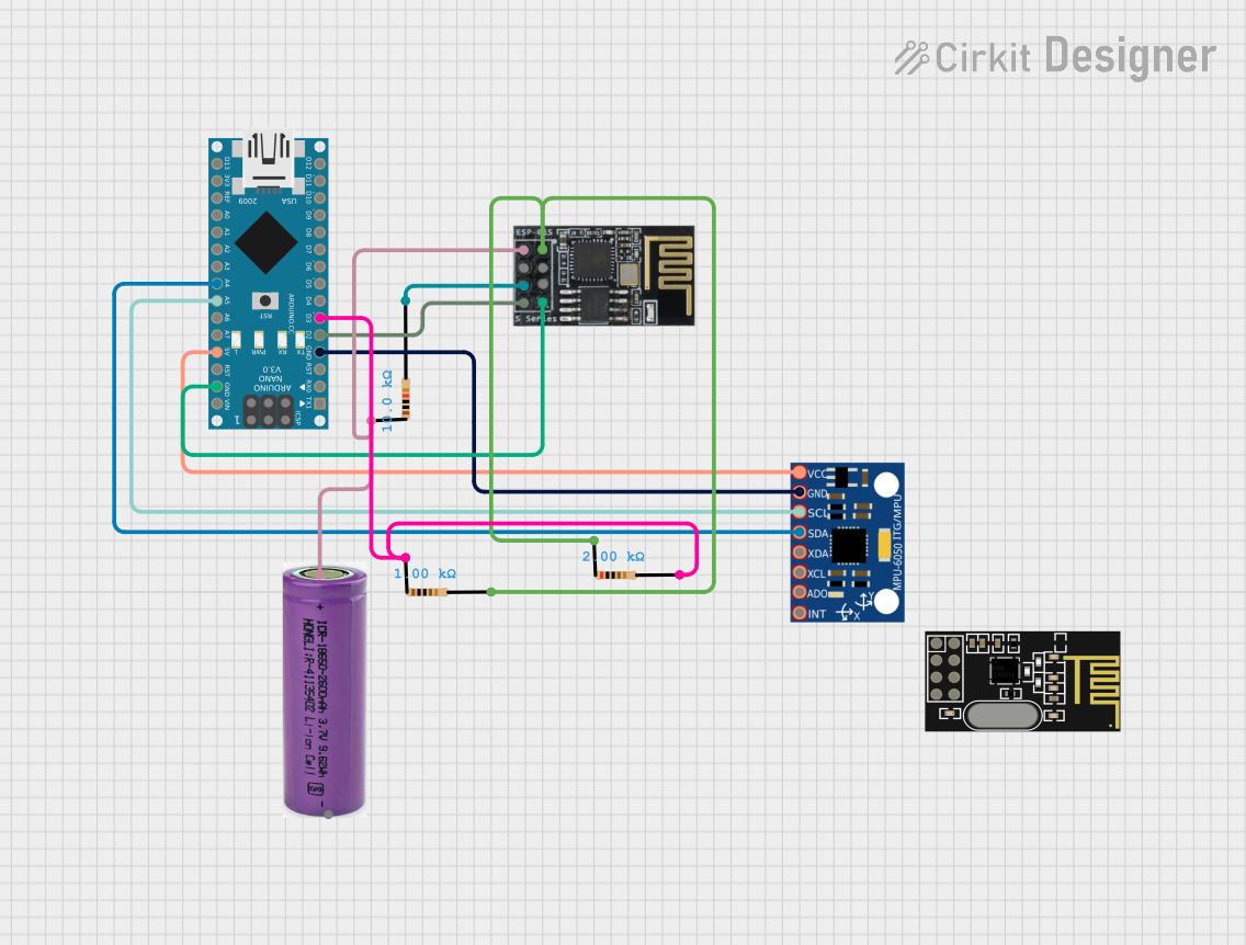
Circuit Documentation
Summary
This document provides a detailed overview of a hand gesture-controlled indicator glove circuit. The circuit uses an MPU6050 sensor to detect hand gestures and control an indicator LED. The ESP8266 WiFi module is used for wireless communication. The Arduino Nano serves as the main microcontroller, interfacing with the MPU6050 sensor and the ESP8266 WiFi module.
Component List
Resistor (10k Ohms)
- Pins: pin1, pin2
- Description: Provides necessary resistance in the circuit.
Arduino Nano
- Pins: D1/TX, D0/RX, RESET, GND, D2, D3, D4, D5, D6, D7, D8, D9, D10, D11/MOSI, D12/MISO, VIN, 5V, A7, A6, A5, A4, A3, A2, A1, A0, AREF, 3V3, D13/SCK
- Description: Main microcontroller for the circuit.
MPU-6050
- Pins: VCC, GND, SCL, SDA, XDA, XCL, AD0, INT
- Description: 6-axis motion tracking device.
NRF24L01
- Pins: IRQ (not used), MOSI, CSN, VCC (3V), GND, CE, SCK, MISO
- Description: Wireless transceiver module.
WiFi module ESP8266-01
- Pins: RX, GPIO0, GPIO2, GND, +3V3, Reset, CH-PD Chip power down, TX
- Description: WiFi module for wireless communication.
Resistor (1k Ohms)
- Pins: pin1, pin2
- Description: Provides necessary resistance in the circuit.
Resistor (2k Ohms)
- Pins: pin1, pin2
- Description: Provides necessary resistance in the circuit.
3.3V Battery
- Pins: +, -
- Description: Power source for the circuit.
Wiring Details
Resistor (10k Ohms)
pin1 is connected to:
- +3V3 pin of the WiFi module ESP8266-01
-
- pin of the 3.3V battery
pin2 is connected to:
- CH-PD Chip power down pin of the WiFi module ESP8266-01
Arduino Nano
GND is connected to:
- GND pin of the MPU-6050
- GND pin of the WiFi module ESP8266-01
D2 is connected to:
- TX pin of the WiFi module ESP8266-01
D3 is connected to:
- pin1 of the 1k Ohms resistor
- pin2 of the 2k Ohms resistor
5V is connected to:
- VCC pin of the MPU-6050
A5 is connected to:
- SCL pin of the MPU-6050
A4 is connected to:
- SDA pin of the MPU-6050
MPU-6050
GND is connected to:
- GND pin of the Arduino Nano
VCC is connected to:
- 5V pin of the Arduino Nano
SCL is connected to:
- A5 pin of the Arduino Nano
SDA is connected to:
- A4 pin of the Arduino Nano
NRF24L01
- Not connected in this circuit.
WiFi module ESP8266-01
+3V3 is connected to:
- pin1 of the 10k Ohms resistor
-
- pin of the 3.3V battery
CH-PD Chip power down is connected to:
- pin2 of the 10k Ohms resistor
TX is connected to:
- D2 pin of the Arduino Nano
GND is connected to:
- GND pin of the Arduino Nano
RX is connected to:
- pin2 of the 1k Ohms resistor
- pin1 of the 2k Ohms resistor
Resistor (1k Ohms)
pin1 is connected to:
- pin2 of the 2k Ohms resistor
- D3 pin of the Arduino Nano
pin2 is connected to:
- RX pin of the WiFi module ESP8266-01
Resistor (2k Ohms)
pin1 is connected to:
- pin2 of the 1k Ohms resistor
- RX pin of the WiFi module ESP8266-01
pin2 is connected to:
- pin1 of the 1k Ohms resistor
- D3 pin of the Arduino Nano
3.3V Battery
+ is connected to:
- pin1 of the 10k Ohms resistor
- +3V3 pin of the WiFi module ESP8266-01
- is not connected in this circuit.
Code Documentation
/*
 * Hand Gesture Controlled Indicator Glove
 * This Arduino sketch uses an MPU6050 sensor to detect hand gestures and
 * control an indicator LED. The ESP8266 WiFi module is used for wireless
 * communication. The LED will blink based on left and right hand gestures.
 */

#include <Wire.h>
#include <MPU6050.h>
#include <ESP8266WiFi.h>

MPU6050 mpu;
const int ledPin = 13; // Onboard LED on Arduino Nano

void setup() {
  // Initialize serial communication
  Serial.begin(9600);
  // Initialize I2C communication
  Wire.begin();
  // Initialize MPU6050
  mpu.initialize();
  // Check MPU6050 connection
  if (!mpu.testConnection()) {
    Serial.println("MPU6050 connection failed");
    while (1);
  }
  // Initialize LED pin
  pinMode(ledPin, OUTPUT);
  // Initialize WiFi module
  WiFi.begin("SSID", "PASSWORD");
  while (WiFi.status() != WL_CONNECTED) {
    delay(1000);
    Serial.println("Connecting to WiFi...");
  }
  Serial.println("Connected to WiFi");
}

void loop() {
  // Read accelerometer and gyroscope data
  mpu.getMotion6(&ax, &ay, &az, &gx, &gy, &gz);
  // Determine hand gesture
  if (ax > 10000) {
    // Right hand gesture detected
    digitalWrite(ledPin, HIGH);
    delay(500);
    digitalWrite(ledPin, LOW);
  } else if (ax < -10000) {
    // Left hand gesture detected
    digitalWrite(ledPin, HIGH);
    delay(500);
    digitalWrite(ledPin, LOW);
  }
  delay(100); // Small delay to avoid rapid blinking
}
This code initializes the MPU6050 sensor and the ESP8266 WiFi module. It reads accelerometer and gyroscope data to detect hand gestures and controls an indicator LED based on the detected gestures. The LED blinks when a left or right hand gesture is detected.