
Arduino UNO-Based Automatic Light Control with PIR Sensor and Relay
View and Edit Project In Cirkit Designer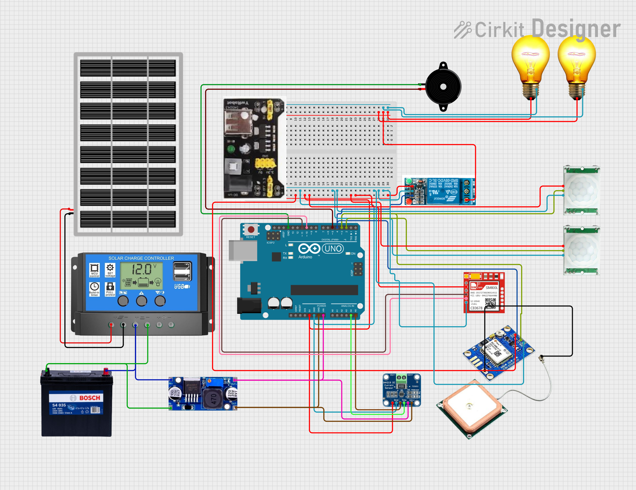
Circuit Documentation
Summary
This circuit is designed to control an automatic light using a PIR motion sensor and a relay. When the PIR sensor detects motion, the relay activates to turn on an AC bulb. The circuit also includes a GPS module, a GSM module, a current sensor, a piezo speaker, and a solar charge controller for power management. The Arduino UNO microcontroller is used to control the entire system.
Component List
PIR/Motion Sensor
- Pins: GND, OUTPUT, VCC
- Description: Detects motion and outputs a signal when motion is detected.
AC Bulb
- Pins: P, N
- Description: Standard AC bulb controlled by the relay.
Arduino UNO
- Pins: UNUSED, IOREF, Reset, 3.3V, 5V, GND, Vin, A0, A1, A2, A3, A4, A5, SCL, SDA, AREF, D13, D12, D11, D10, D9, D8, D7, D6, D5, D4, D3, D2, D1, D0
- Description: Microcontroller used to control the circuit.
Piezo Speaker
- Pins: pin1, pin2
- Description: Emits sound when activated.
Solar Charge Controller
- Pins: Solar Cell +, Solar Cell -, Battery +, Battery -, Load +, Load -
- Description: Manages the charging of the battery from the solar panel.
5V Relay
- Pins: Normally Open, Common terminal, Normally Closed, In, GND, VCC
- Description: Controls the AC bulb based on the signal from the Arduino.
MB102 Breadboard Power Supply Module 3.3V/5V
- Pins: GND, 3.3V, 5V
- Description: Provides regulated 3.3V and 5V power supply.
LM2596
- Pins: IN, OUT
- Description: DC-DC buck converter used to step down voltage.
INA219
- Pins: VCC, GND, SCL, SDA, VIN -, VIN +
- Description: Current sensor used to measure current and voltage.
12V 200Ah Battery
- Pins: GND, 12V
- Description: Provides power to the circuit.
Solar Panel
- Pins: gnd, vcc
- Description: Generates power from sunlight.
Sim800l
- Pins: NET, RST, VCC, RXD, TXD, GND
- Description: GSM module used for communication.
Ublox NEO-M8N GPS module
- Pins: RF coaxial cable connectors, VCC, RX, TX, GND
- Description: GPS module used for location tracking.
Wiring Details
PIR/Motion Sensor
- GND connected to Arduino UNO GND
- OUTPUT connected to Arduino UNO D3
- VCC connected to Arduino UNO 5V
AC Bulb
- P connected to 5V Relay Normally Open
- N connected to AC Bulb N
Arduino UNO
- 5V connected to VCC of PIR/Motion Sensor, Ublox NEO-M8N GPS module, INA219, Sim800l, and 5V Relay
- GND connected to GND of PIR/Motion Sensor, Ublox NEO-M8N GPS module, INA219, Sim800l, 5V Relay, and Piezo Speaker pin1
- D3 connected to OUTPUT of PIR/Motion Sensor
- D4 connected to In of 5V Relay
- Vin connected to VIN - of INA219 and OUT of LM2596
- A4 connected to SDA of INA219
- A5 connected to SCL of INA219
- D11 connected to RXD of Sim800l
- D10 connected to TXD of Sim800l
- D5 connected to pin2 of Piezo Speaker
- D2 connected to OUTPUT of PIR/Motion Sensor
Piezo Speaker
- pin1 connected to Arduino UNO GND
- pin2 connected to Arduino UNO D5
Solar Charge Controller
- Solar Cell + connected to vcc of Solar Panel
- Solar Cell - connected to gnd of Solar Panel
- Battery + connected to 12V of 12V 200Ah Battery
- Battery - connected to GND of 12V 200Ah Battery
5V Relay
- Normally Open connected to P of AC Bulb
- Common terminal connected to AC power source
- In connected to Arduino UNO D4
- GND connected to Arduino UNO GND
- VCC connected to Arduino UNO 5V
LM2596
- IN connected to 12V and GND of 12V 200Ah Battery
- OUT connected to VIN - and VIN + of INA219
INA219
- VCC connected to Arduino UNO 5V
- GND connected to Arduino UNO GND
- SCL connected to Arduino UNO A5
- SDA connected to Arduino UNO A4
- VIN - connected to OUT of LM2596
- VIN + connected to Arduino UNO GND
12V 200Ah Battery
- 12V connected to IN of LM2596 and Battery + of Solar Charge Controller
- GND connected to IN of LM2596 and Battery - of Solar Charge Controller
Solar Panel
- gnd connected to Solar Cell - of Solar Charge Controller
- vcc connected to Solar Cell + of Solar Charge Controller
Sim800l
- VCC connected to Arduino UNO 5V
- GND connected to Arduino UNO GND
- RXD connected to Arduino UNO D11
- TXD connected to Arduino UNO D10
Ublox NEO-M8N GPS module
- VCC connected to Arduino UNO 5V
- GND connected to Arduino UNO GND
- TX connected to Arduino UNO D3
- RX connected to Arduino UNO D4
Code Documentation
/*
 * Proyecto: Luz Automática con Sensor PIR y Relé
 * Descripción: Este código controla una luz automática utilizando un sensor PIR
 * y un relé. Cada vez que el sensor PIR detecta movimiento, el relé se activa
 * para encender una bombilla. Además, el código cuenta el número de veces que
 * se detecta una persona y lo imprime en el monitor serie.
 */

// Definición de pines
const int pirPin = 3; // Pin de salida del sensor PIR
const int relayPin = 4; // Pin de entrada del relé

// Variables
int motionDetected = 0; // Contador de detecciones de movimiento

void setup() {
  // Configuración de pines
  pinMode(pirPin, INPUT);
  pinMode(relayPin, OUTPUT);
  // Inicialización del monitor serie
  Serial.begin(9600);
  // Inicialización del relé en estado apagado
  digitalWrite(relayPin, LOW);
}

void loop() {
  // Lectura del estado del sensor PIR
  int pirState = digitalRead(pirPin);
  if (pirState == HIGH) {
    // Si se detecta movimiento
    digitalWrite(relayPin, HIGH); // Encender la luz
    motionDetected++; // Incrementar el contador
    Serial.print("Movimiento detectado: ");
    Serial.println(motionDetected);
    delay(5000); // Mantener la luz encendida por 5 segundos
  } else {
    // Si no se detecta movimiento
    digitalWrite(relayPin, LOW); // Apagar la luz
  }
  delay(100); // Pequeña espera para evitar rebotes
}
This code controls an automatic light using a PIR sensor and a relay. When motion is detected, the relay is activated to turn on the light, and the number of detections is printed to the serial monitor.