
Arduino UNO-Based Color Sensor with LCD Display and Stepper Motor Control
View and Edit Project In Cirkit Designer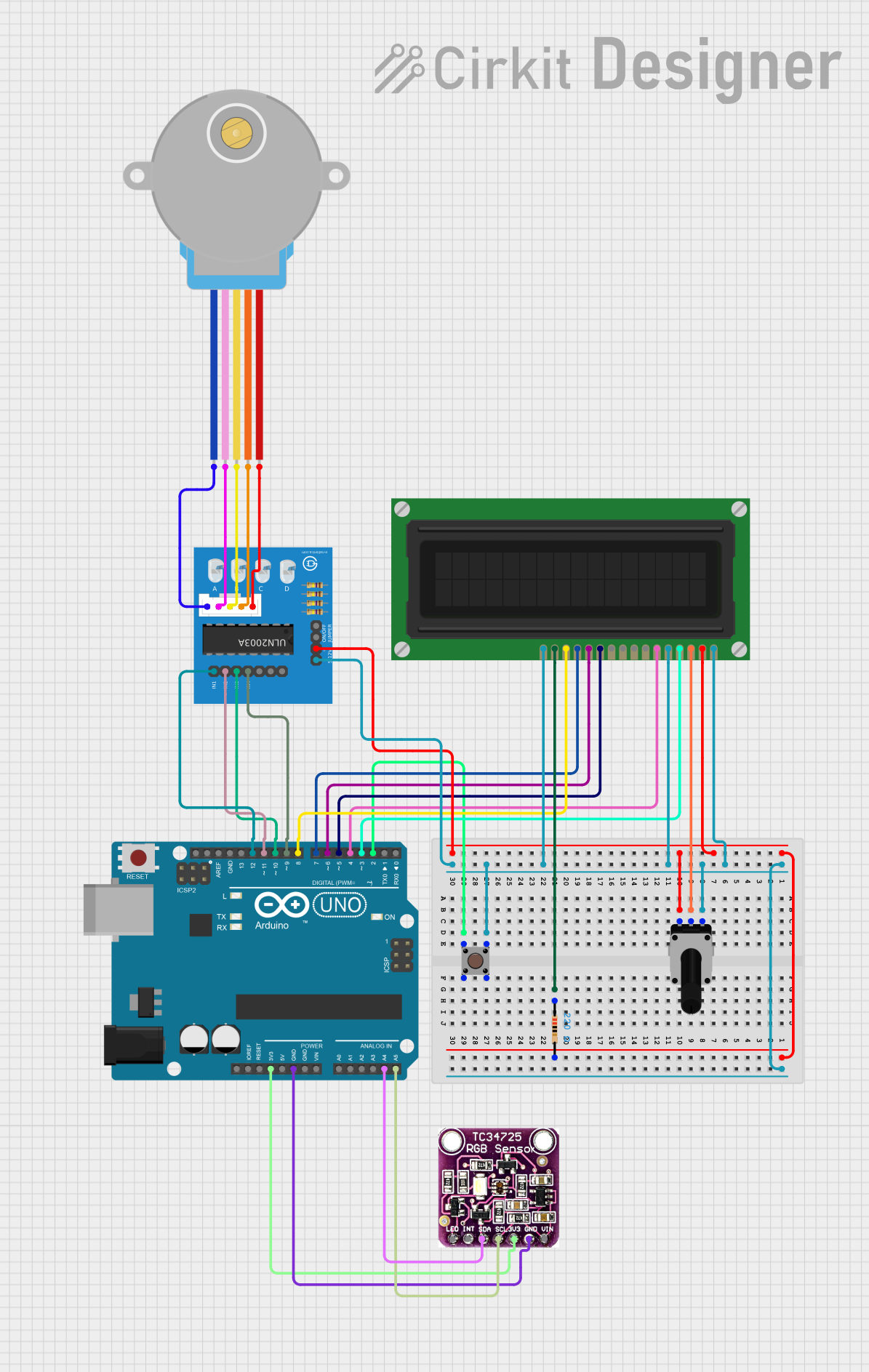
Circuit Documentation
Summary
This circuit involves an Arduino UNO microcontroller interfacing with various components including an LCD display, a rotary potentiometer, a pushbutton, a TCS3472 color light-to-digital converter, a ULN2003A breakout board, and a 28BYJ-48 stepper motor. The circuit is designed to demonstrate basic interfacing and control of these components using the Arduino platform.
Component List
Arduino UNO
- Description: A microcontroller board based on the ATmega328P.
- Pins: UNUSED, IOREF, Reset, 3.3V, 5V, GND, Vin, A0, A1, A2, A3, A4, A5, SCL, SDA, AREF, D13, D12, D11, D10, D9, D8, D7, D6, D5, D4, D3, D2, D1, D0
LCD Display (16 pin)
- Description: A 16-pin LCD display module.
- Pins: VSS, VDD, VO, RS, R_W, E, DB0, DB1, DB2, DB3, DB4, DB5, DB6, DB7, A, K
Rotary Potentiometer
- Description: A variable resistor used to adjust voltage levels.
- Pins: leg1, wiper, leg2
- Properties: Resistance: 10000 Ohms
TCS3472 COLOR LIGHT-TO-DIGITAL CONVERTER with IR FILTER
- Description: A color sensor that converts light to digital values.
- Pins: LED, INT, SDA, SCL, 3V3, GND, VIN
Pushbutton
- Description: A simple pushbutton switch.
- Pins: Pin 3 (out), Pin 4 (out), Pin 1 (in), Pin 2 (in)
Resistor
- Description: A passive electrical component that resists the flow of current.
- Pins: pin1, pin2
- Properties: Resistance: 220 Ohms
ULN2003A breakout board
- Description: A Darlington transistor array used to drive high-current loads.
- Pins: In 1, In 2, In 3, In 4, In 5, In 6, In 7, 0V, +5V, ON/OFF jumper switch, BLUE wire, PINK wire, YELLOW wire, ORANGE wire, RED wire
28BYJ-48 Stepper Motor
- Description: A small stepper motor used for precise control of angular position.
- Pins: BLUE, PINK, YELLOW, ORANGE, RED
Wiring Details
Arduino UNO
- D2 to Pushbutton Pin 1 (in)
- 3.3V to TCS3472 COLOR LIGHT-TO-DIGITAL CONVERTER with IR FILTER 3V3
- GND to TCS3472 COLOR LIGHT-TO-DIGITAL CONVERTER with IR FILTER GND
- A4 to TCS3472 COLOR LIGHT-TO-DIGITAL CONVERTER with IR FILTER SDA
- A5 to TCS3472 COLOR LIGHT-TO-DIGITAL CONVERTER with IR FILTER SCL
- D12 to ULN2003A breakout board In 1
- D11 to ULN2003A breakout board In 2
- D10 to ULN2003A breakout board In 3
- D9 to ULN2003A breakout board In 4
- D8 to LCD Display (16 pin) DB7
- D7 to LCD Display (16 pin) DB6
- D6 to LCD Display (16 pin) DB5
- D5 to LCD Display (16 pin) DB4
- D4 to LCD Display (16 pin) E
- D3 to LCD Display (16 pin) RS
LCD Display (16 pin)
- VSS to Rotary Potentiometer leg1
- R_W to Rotary Potentiometer leg1
- K to Rotary Potentiometer leg1
- VO to Rotary Potentiometer wiper
- VDD to Rotary Potentiometer leg2
- VDD to Resistor pin2
- A to Resistor pin1
Rotary Potentiometer
- leg1 to Pushbutton Pin 3 (out)
- leg1 to LCD Display (16 pin) VSS
- leg1 to LCD Display (16 pin) R_W
- leg1 to LCD Display (16 pin) K
- wiper to LCD Display (16 pin) VO
- leg2 to Resistor pin2
- leg2 to LCD Display (16 pin) VDD
Pushbutton
- Pin 3 (out) to Rotary Potentiometer leg1
- Pin 1 (in) to Arduino UNO D2
Resistor
- pin2 to Rotary Potentiometer leg2
- pin2 to LCD Display (16 pin) VDD
- pin1 to LCD Display (16 pin) A
TCS3472 COLOR LIGHT-TO-DIGITAL CONVERTER with IR FILTER
- 3V3 to Arduino UNO 3.3V
- GND to Arduino UNO GND
- SDA to Arduino UNO A4
- SCL to Arduino UNO A5
ULN2003A breakout board
- 0V to Rotary Potentiometer leg1
- +5V to Rotary Potentiometer leg2
- In 1 to Arduino UNO D12
- In 2 to Arduino UNO D11
- In 3 to Arduino UNO D10
- In 4 to Arduino UNO D9
- BLUE wire to 28BYJ-48 Stepper Motor BLUE
- PINK wire to 28BYJ-48 Stepper Motor PINK
- YELLOW wire to 28BYJ-48 Stepper Motor YELLOW
- ORANGE wire to 28BYJ-48 Stepper Motor ORANGE
- RED wire to 28BYJ-48 Stepper Motor RED
28BYJ-48 Stepper Motor
- BLUE to ULN2003A breakout board BLUE wire
- PINK to ULN2003A breakout board PINK wire
- YELLOW to ULN2003A breakout board YELLOW wire
- ORANGE to ULN2003A breakout board ORANGE wire
- RED to ULN2003A breakout board RED wire
Documented Code
Arduino UNO Code (sketch.ino)
void setup() {
  // put your setup code here, to run once:

}

void loop() {
  // put your main code here, to run repeatedly:

}
Additional Documentation (documentation.txt)
This documentation provides a comprehensive overview of the circuit, including a detailed list of components, their wiring connections, and the code used for the Arduino UNO microcontroller.