Cirkit Designer
Your all-in-one circuit design IDE
Home /
Project Documentation
Arduino UNO Controlled Touch Interface with OLED Display and Servo Feedback

Circuit Documentation
Summary
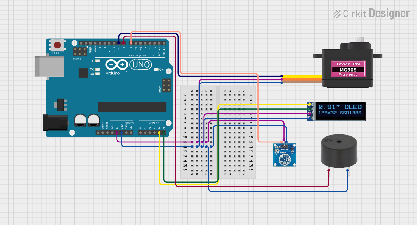
The circuit in question is designed to interface an Arduino UNO with a touch sensor, an OLED display, a servomotor, and a buzzer. The Arduino UNO serves as the central microcontroller unit, managing input from the touch sensor and controlling the display, servomotor, and buzzer based on programmed logic. The touch sensor provides user input, the OLED display offers a visual interface, the servomotor enables mechanical movement, and the buzzer can generate audio signals.
Component List
Touch Sensor
- Name: Touch Sensor
- Pins: IO, VCC, GND
- Description: A sensor that detects touch input.
- Purpose: To provide user input to the microcontroller.
Arduino UNO
- Name: Arduino UNO
- Pins: UNUSED, IOREF, Reset, 3.3V, 5V, GND, Vin, A0-A5, SCL, SDA, AREF, D0-D13
- Description: A microcontroller board based on the ATmega328P.
- Purpose: To serve as the central processing unit of the circuit, interfacing with all other components.
OLED Display (128x32)
- Name: OLED Display
- Pins: SDA, SCL, VCC, GND
- Description: A small screen capable of displaying graphics and text.
- Purpose: To provide a visual output for the user.
Servomotor MG90S
- Name: Servomotor MG90S
- Pins: SIG, VCC, GND
- Description: A small servo capable of precise angular movement.
- Purpose: To perform mechanical actions as directed by the microcontroller.
Buzzer
- Name: Buzzer
- Pins: PIN, GND
- Description: An electronic buzzer capable of emitting sound.
- Purpose: To provide audio feedback or alerts.
Wiring Details
Touch Sensor
- IO: Connected to Arduino UNO's D7
- VCC: Connected to Arduino UNO's 5V
- GND: Connected to Arduino UNO's GND
Arduino UNO
- 5V: Provides power to the touch sensor, OLED display, and servomotor
- GND: Common ground for all components
- A4 (SDA): Connected to OLED display's SDA
- A5 (SCL): Connected to OLED display's SCL
- D7: Connected to touch sensor's IO
- D9: Connected to servomotor's SIG
- D8: Connected to buzzer's PIN
OLED Display (128x32)
- SDA: Connected to Arduino UNO's A4
- SCL: Connected to Arduino UNO's A5
- VCC: Connected to Arduino UNO's 5V
- GND: Connected to Arduino UNO's GND
Servomotor MG90S
- SIG: Connected to Arduino UNO's D9
- VCC: Connected to Arduino UNO's 5V
- GND: Connected to Arduino UNO's GND
Buzzer
- PIN: Connected to Arduino UNO's D8
- GND: Connected to Arduino UNO's GND
Documented Code
Arduino UNO Code (sketch.ino)
void setup() {
  // put your setup code here, to run once:

}

void loop() {
  // put your main code here, to run repeatedly:

}
Note: The provided code is a template and does not contain any functional logic. It needs to be populated with the specific instructions to control the touch sensor, OLED display, servomotor, and buzzer based on the desired behavior of the circuit.