
Arduino UNO and HC-05 Bluetooth Controlled Motor with Relay and LED Indicator
View and Edit Project In Cirkit Designer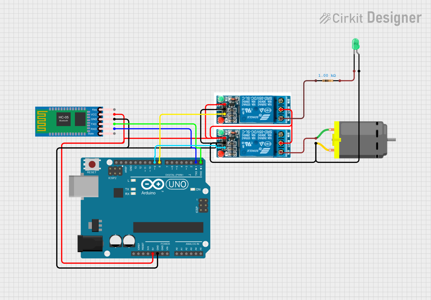
Circuit Documentation
Summary
This circuit integrates an Arduino UNO microcontroller with a HC-05 Bluetooth Module, two 5V relays, a green LED, a DC motor, and a resistor. The Arduino UNO is used as the central processing unit, controlling the relays which in turn control the power flow to the DC motor and the LED. The HC-05 Bluetooth Module allows for wireless communication, potentially to receive commands to control the motor and LED. The resistor is used to limit current to the LED, protecting it from damage.
Component List
Arduino UNO
- Microcontroller board based on the ATmega328P
- It has 14 digital input/output pins, 6 analog inputs, a 16 MHz quartz crystal, a USB connection, a power jack, an ICSP header, and a reset button.
HC-05 Bluetooth Module
- A Bluetooth module for wireless communication
- It has pins for Key, VCC, GND, TXD, RXD, and State.
5V Relay (x2)
- An electromechanical switch used to control a high power circuit with a low power signal
- It has pins for Normally Open, Common terminal, Normally Closed, In, GND, and VCC.
LED: Two Pin (green)
- A green light-emitting diode
- It has two pins: anode and cathode.
DC Motor
- An electric motor that runs on direct current (DC) electricity
- It has two pins for connecting to the power source.
Resistor (1k Ohm)
- A passive two-terminal electrical component that implements electrical resistance as a circuit element
- It has a resistance value of 1000 Ohms.
Wiring Details
Arduino UNO
- 5V: Connected to VCC of both 5V relays and HC-05 Bluetooth Module
- GND: Connected to GND of both 5V relays, HC-05 Bluetooth Module, and the cathode of the LED through a resistor
- D9: Connected to the 'In' pin of one 5V relay
- D8: Connected to the 'In' pin of the other 5V relay
- D1: Connected to RXD of HC-05 Bluetooth Module
- D0: Connected to TXD of HC-05 Bluetooth Module
HC-05 Bluetooth Module
- VCC: Connected to 5V of Arduino UNO
- GND: Connected to GND of Arduino UNO
- TXD: Connected to D0 of Arduino UNO
- RXD: Connected to D1 of Arduino UNO
5V Relay
- VCC: Connected to 5V of Arduino UNO
- GND: Connected to GND of Arduino UNO
- In: Connected to D9 of Arduino UNO (for one relay) and D8 of Arduino UNO (for the other relay)
- Common terminal: Connected to VCC (internally connected to both relays)
- Normally Open: One relay is connected to pin 1 of the DC Motor, and the other is connected to the anode of the LED through a resistor
LED: Two Pin (green)
- Anode: Connected to Normally Open of one 5V relay through a resistor
- Cathode: Connected to GND of Arduino UNO through a resistor
DC Motor
- Pin 1: Connected to Normally Open of one 5V relay
- Pin 2: Connected to GND of Arduino UNO
Resistor (1k Ohm)
- Pin1: Connected to Normally Open of one 5V relay
- Pin2: Connected to the cathode of the LED
Documented Code
void setup() {
  // put your setup code here, to run once:

}

void loop() {
  // put your main code here, to run repeatedly:

}
The provided code is a template for the Arduino UNO microcontroller. The setup() function is called once when the microcontroller is first powered on or reset. The loop() function is called repeatedly and contains the main logic of the program. The actual implementation details need to be filled in based on the desired behavior of the circuit.