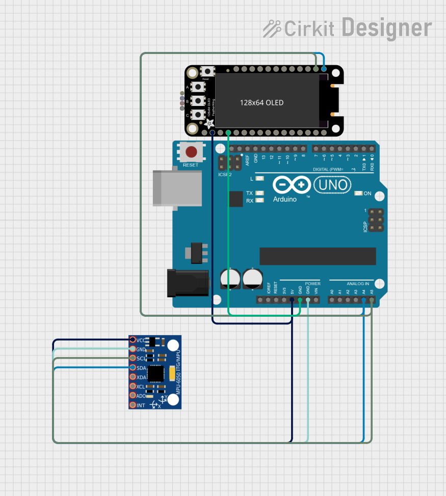
Arduino UNO Based Motion Tracking Display with MPU-6050 and OLED

Circuit Documentation
Summary of the Circuit
This circuit integrates an Arduino UNO microcontroller with an Adafruit 128x64 OLED FeatherWing display and an MPU-6050 accelerometer and gyroscope module. The Arduino UNO serves as the central processing unit, managing data communication between the MPU-6050 sensor and the OLED display. The MPU-6050 provides real-time acceleration and rotation data, which is then displayed on the OLED screen. The circuit utilizes the I2C communication protocol, facilitated by the SDA (Serial Data Line) and SCL (Serial Clock Line) connections shared among the devices.
Component List
Arduino UNO
- Description: A microcontroller board based on the ATmega328P, featuring digital and analog I/O pins.
- Purpose: Acts as the central controller for the circuit, interfacing with the sensor and display.
Adafruit 128x64 OLED FeatherWing
- Description: A small OLED display with 128x64 pixel resolution, compatible with the FeatherWing form factor.
- Purpose: Displays the sensor data received from the MPU-6050 through the Arduino UNO.
MPU-6050
- Description: A motion tracking device that combines a 3-axis gyroscope and a 3-axis accelerometer.
- Purpose: Provides real-time motion tracking data to the Arduino UNO for processing and display.
Wiring Details
Arduino UNO
- 5V: Powers the Adafruit OLED FeatherWing and MPU-6050.
- GND: Common ground for the circuit.
- A4 (SDA): I2C data line connected to the SDA pins of the OLED display and MPU-6050.
- A5 (SCL): I2C clock line connected to the SCL pins of the OLED display and MPU-6050.
Adafruit 128x64 OLED FeatherWing
- 3.3V: Connected to the 5V output from the Arduino UNO for power.
- GND: Connected to the common ground.
- SDA: I2C data line connected to the Arduino UNO's A4 pin.
- SCL: I2C clock line connected to the Arduino UNO's A5 pin.
MPU-6050
- VCC: Powered by the 5V output from the Arduino UNO.
- GND: Connected to the common ground.
- SDA: I2C data line connected to the Arduino UNO's A4 pin.
- SCL: I2C clock line connected to the Arduino UNO's A5 pin.
Documented Code
#include <Wire.h>
#include <MPU6050.h>
#include <Adafruit_GFX.h>
#include <Adafruit_SSD1306.h>

#define SCREEN_WIDTH 128
#define SCREEN_HEIGHT 64
#define OLED_RESET    -1
Adafruit_SSD1306 display(SCREEN_WIDTH, SCREEN_HEIGHT, &Wire, OLED_RESET);

// Create MPU6050 object
MPU6050 mpu;

void setup() {
  Serial.begin(115200);

  // Initialize MPU6050
  Wire.begin();
  mpu.initialize();
  if (!mpu.testConnection()) {
    Serial.println("MPU6050 connection failed");
    while (1);
  }

  // Initialize OLED display
  if(!display.begin(SSD1306_I2C_ADDRESS, 0x3D)) {
    Serial.println(F("SSD1306 allocation failed"));
    for(;;);
  }
  display.display();
  delay(2000);
  display.clearDisplay();
}

void loop() {
  // Read raw accelerometer and gyroscope data
  Vector accel = mpu.getAcceleration();
  Vector gyro = mpu.getRotation();

  float ax = accel.x;
  float ay = accel.y;
  float az = accel.z;
  float gx = gyro.x;
  float gy = gyro.y;
  float gz = gyro.z;

  // Clear display
  display.clearDisplay();

  // Print data on OLED
  display.setCursor(0,0);
  display.print("Accel X: ");
  display.println(ax);
  display.print("Accel Y: ");
  display.println(ay);
  display.print("Accel Z: ");
  display.println(az);
  display.print("Gyro X: ");
  display.println(gx);
  display.print("Gyro Y: ");
  display.println(gy);
  display.print("Gyro Z: ");
  display.println(gz);

  display.display();

  delay(500); // Update every 500ms
}
This code initializes the MPU6050 sensor and the Adafruit SSD1306 OLED display. It then enters a loop where it reads the acceleration and rotation data from the MPU6050 and displays it on the OLED screen. The display is updated every 500 milliseconds.