
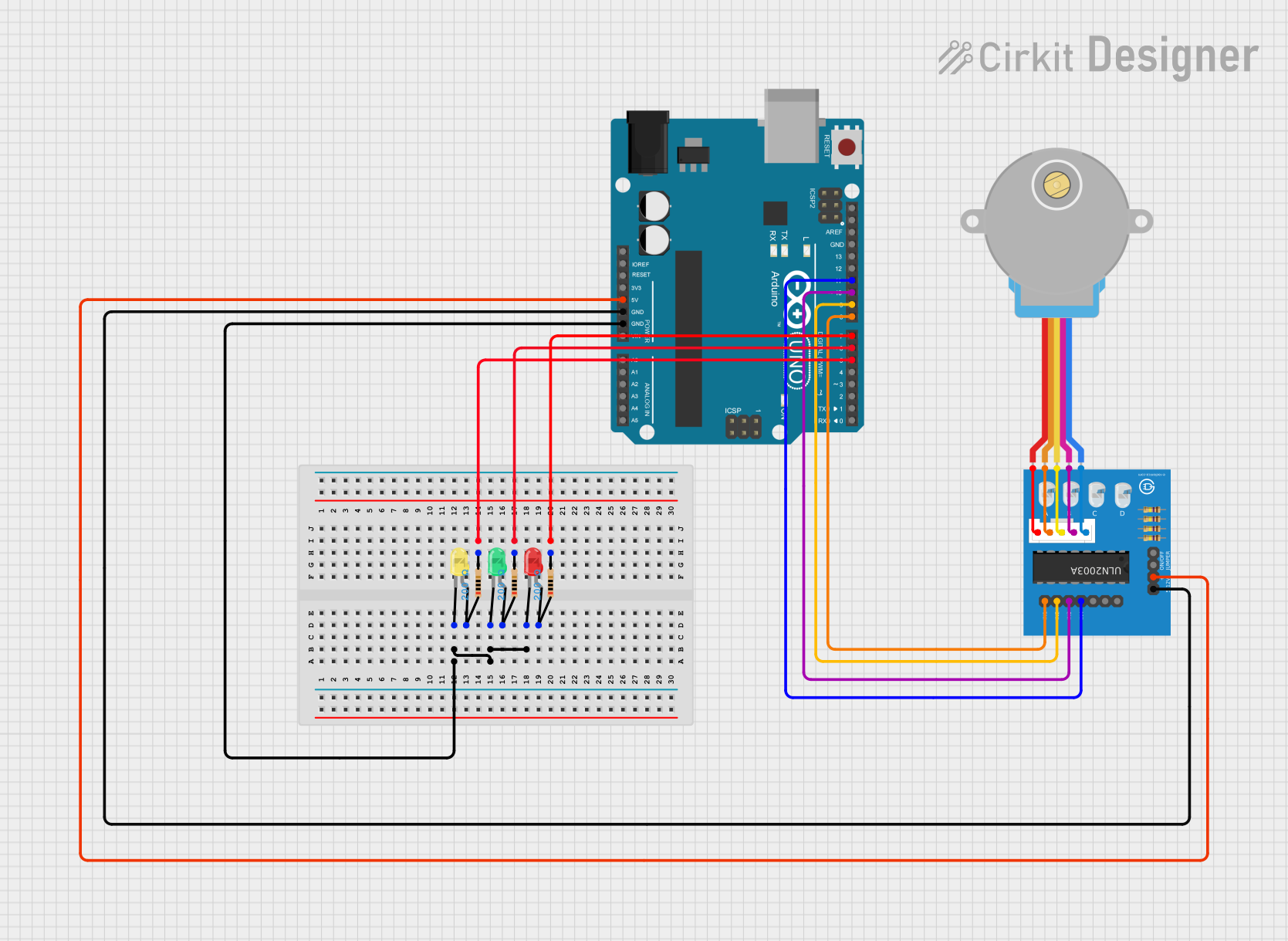
Circuit Documentation
Summary
This circuit involves an Arduino UNO microcontroller, a ULN2003A breakout board, an Adafruit Gear-Reduced Stepper Motor, and three LEDs (red, green, and yellow) each connected through a 200 Ohm resistor. The Arduino UNO controls the LEDs and the stepper motor via the ULN2003A breakout board.
Component List
Arduino UNO
- Description: A microcontroller board based on the ATmega328P.
- Pins: UNUSED, IOREF, Reset, 3.3V, 5V, GND, Vin, A0, A1, A2, A3, A4, A5, SCL, SDA, AREF, D13, D12, D11, D10, D9, D8, D7, D6, D5, D4, D3, D2, D1, D0
Adafruit Gear-Reduced Stepper Motor (small)
- Description: A small stepper motor with gear reduction for increased torque.
- Pins: RED, ORANGE, YELLOW, PINK, BLUE
ULN2003A Breakout Board
- Description: A Darlington transistor array used to drive the stepper motor.
- Pins: In 1, In 2, In 3, In 4, In 5, In 6, In 7, 0V, +5V, ON/OFF jumper switch, BLUE wire, PINK wire, YELLOW wire, ORANGE wire, RED wire
LED: Two Pin (red)
- Description: A red LED.
- Pins: cathode, anode
LED: Two Pin (green)
- Description: A green LED.
- Pins: cathode, anode
LED: Two Pin (yellow)
- Description: A yellow LED.
- Pins: cathode, anode
Resistor (200 Ohms)
- Description: A resistor with a resistance of 200 Ohms.
- Pins: pin1, pin2
Wiring Details
Arduino UNO
GND connected to:
- Cathode of yellow LED
- Cathode of green LED
- Cathode of red LED
- 0V of ULN2003A breakout board
5V connected to:
- +5V of ULN2003A breakout board
D5 connected to:
- pin2 of a 200 Ohm resistor (connected to the anode of the yellow LED)
D6 connected to:
- pin2 of a 200 Ohm resistor (connected to the anode of the green LED)
D7 connected to:
- pin2 of a 200 Ohm resistor (connected to the anode of the red LED)
D8 connected to:
- In 1 of ULN2003A breakout board
D9 connected to:
- In 2 of ULN2003A breakout board
D10 connected to:
- In 3 of ULN2003A breakout board
D11 connected to:
- In 4 of ULN2003A breakout board
Adafruit Gear-Reduced Stepper Motor (small)
RED connected to:
- BLUE wire of ULN2003A breakout board
ORANGE connected to:
- PINK wire of ULN2003A breakout board
YELLOW connected to:
- YELLOW wire of ULN2003A breakout board
PINK connected to:
- ORANGE wire of ULN2003A breakout board
BLUE connected to:
- RED wire of ULN2003A breakout board
ULN2003A Breakout Board
0V connected to:
- GND of Arduino UNO
+5V connected to:
- 5V of Arduino UNO
In 1 connected to:
- D8 of Arduino UNO
In 2 connected to:
- D9 of Arduino UNO
In 3 connected to:
- D10 of Arduino UNO
In 4 connected to:
- D11 of Arduino UNO
BLUE wire connected to:
- RED of stepper motor
PINK wire connected to:
- ORANGE of stepper motor
YELLOW wire connected to:
- YELLOW of stepper motor
ORANGE wire connected to:
- PINK of stepper motor
RED wire connected to:
- BLUE of stepper motor
LED: Two Pin (red)
cathode connected to:
- GND of Arduino UNO
anode connected to:
- pin1 of a 200 Ohm resistor (connected to D7 of Arduino UNO)
LED: Two Pin (green)
cathode connected to:
- GND of Arduino UNO
anode connected to:
- pin1 of a 200 Ohm resistor (connected to D6 of Arduino UNO)
LED: Two Pin (yellow)
cathode connected to:
- GND of Arduino UNO
anode connected to:
- pin1 of a 200 Ohm resistor (connected to D5 of Arduino UNO)
Resistor (200 Ohms)
pin1 connected to:
- Anode of the corresponding LED
pin2 connected to:
- D5, D6, or D7 of Arduino UNO (depending on the LED)
Documented Code
Arduino UNO Code
void setup() {
  // put your setup code here, to run once:

}

void loop() {
  // put your main code here, to run repeatedly:

}
This code is a basic template for the Arduino UNO. The setup() function is where you initialize your components, and the loop() function is where you place the code that needs to run continuously.