
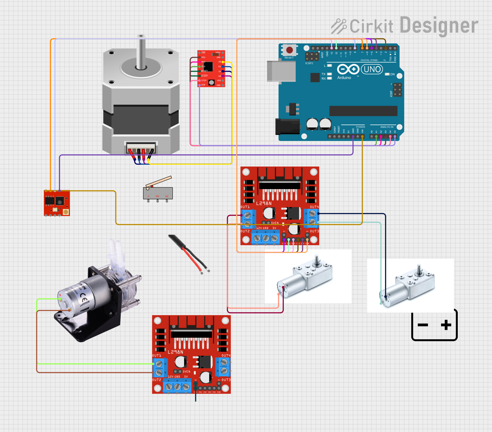
Circuit Documentation
Summary
This circuit involves an Arduino UNO microcontroller, an ESP8266 WiFi module, a stepper motor with its driver, two DC motors with their drivers, a peristaltic pump, and a 12V battery. The Arduino UNO controls the motors and communicates with the ESP8266 module. The L298N motor drivers are used to drive the DC motors and the peristaltic pump, while the A4988 driver is used for the stepper motor.
Component List
12V Battery
- Description: Provides power to the circuit.
- Pins: +, -
Arduino UNO
- Description: Microcontroller used to control the circuit.
- Pins: UNUSED, IOREF, Reset, 3.3V, 5V, GND, Vin, A0, A1, A2, A3, A4, A5, SCL, SDA, AREF, D13, D12, D11, D10, D9, D8, D7, D6, D5, D4, D3, D2, D1, D0
Stepper Motor (Bipolar)
- Description: Motor used for precise control of rotation.
- Pins: D, B, C, A
L298N DC Motor Driver
- Description: Driver used to control DC motors.
- Pins: OUT1, OUT2, 12V, GND, 5V, OUT3, OUT4, 5V-ENA-JMP-I, 5V-ENA-JMP-O, +5V-J1, +5V-J2, ENA, IN1, IN2, IN3, IN4, ENB
AC Wire
- Description: Provides AC power.
- Pins: GND, Phase
Peristaltic Pump
- Description: Pump used for fluid transfer.
- Pins: +, -
A4988 Stepper Motor Driver (Red)
- Description: Driver used to control the stepper motor.
- Pins: ENABLE, MS1, MS2, MS3, RESET, SLEEP, STEP, DIR, VMOT, GND, 2B, 2A, 1A, 1B, VDD
Greartisan DC 12V 45RPM Turbo Worm Geared Motor
- Description: DC motor used for high torque applications.
- Pins: +, -
Limit Switch
- Description: Switch used to detect the limit of movement.
- Pins: C, NO, NC
ESP8266 ESP-02 WiFi Module
- Description: WiFi module used for wireless communication.
- Pins: GPIO15, GPIO0, GPIO2, RST, VCC, TXD, RXD, GND
Wiring Details
12V Battery
- +: Connected to the 12V pin of the L298N DC motor driver.
- -: Connected to the GND pin of the L298N DC motor driver.
Arduino UNO
- GND: Connected to the GND pin of the ESP8266 ESP-02 WiFi Module.
- Vin: Connected to the VCC pin of the ESP8266 ESP-02 WiFi Module.
- A1: Connected to the MS3 pin of the A4988 Stepper Motor Driver.
- A2: Connected to the MS2 pin of the A4988 Stepper Motor Driver.
- A3: Connected to the MS1 pin of the A4988 Stepper Motor Driver.
- A4: Connected to the STEP pin of the A4988 Stepper Motor Driver.
- A5: Connected to the DIR pin of the A4988 Stepper Motor Driver.
- D13: Connected to the IN2 pin of the L298N DC motor driver.
- D12: Connected to the IN1 pin of the L298N DC motor driver.
- D8: Connected to the RXD pin of the ESP8266 ESP-02 WiFi Module.
- D7: Connected to the TXD pin of the ESP8266 ESP-02 WiFi Module.
- D6: Connected to the ENB pin of the L298N DC motor driver.
- D5: Connected to the ENA pin of the L298N DC motor driver.
- D4: Connected to the IN4 pin of the L298N DC motor driver.
- D2: Connected to the IN3 pin of the L298N DC motor driver.
Stepper Motor (Bipolar)
- D: Connected to the 2B pin of the A4988 Stepper Motor Driver.
- B: Connected to the 1B pin of the A4988 Stepper Motor Driver.
- C: Connected to the 2A pin of the A4988 Stepper Motor Driver.
- A: Connected to the 1A pin of the A4988 Stepper Motor Driver.
L298N DC Motor Driver
- OUT2: Connected to the - pin of the Greartisan DC 12V 45RPM Turbo Worm Geared Motor.
- OUT1: Connected to the + pin of the Greartisan DC 12V 45RPM Turbo Worm Geared Motor.
- OUT3: Connected to the - pin of the second Greartisan DC 12V 45RPM Turbo Worm Geared Motor.
- OUT4: Connected to the + pin of the second Greartisan DC 12V 45RPM Turbo Worm Geared Motor.
- IN2: Connected to the D13 pin of the Arduino UNO.
- IN1: Connected to the D12 pin of the Arduino UNO.
- ENB: Connected to the D6 pin of the Arduino UNO.
- ENA: Connected to the D5 pin of the Arduino UNO.
- IN4: Connected to the D4 pin of the Arduino UNO.
- IN3: Connected to the D2 pin of the Arduino UNO.
- OUT1: Connected to the + pin of the Peristaltic Pump.
- OUT2: Connected to the - pin of the Peristaltic Pump.
- ENA: Connected to the +5V-J1 pin of the L298N DC motor driver.
AC Wire
- GND: Not connected in this circuit.
- Phase: Not connected in this circuit.
Peristaltic Pump
- +: Connected to the OUT1 pin of the L298N DC motor driver.
- -: Connected to the OUT2 pin of the L298N DC motor driver.
A4988 Stepper Motor Driver (Red)
- MS3: Connected to the A1 pin of the Arduino UNO.
- MS2: Connected to the A2 pin of the Arduino UNO.
- MS1: Connected to the A3 pin of the Arduino UNO.
- STEP: Connected to the A4 pin of the Arduino UNO.
- DIR: Connected to the A5 pin of the Arduino UNO.
- 2B: Connected to the D pin of the Stepper Motor (Bipolar).
- 1B: Connected to the B pin of the Stepper Motor (Bipolar).
- 2A: Connected to the C pin of the Stepper Motor (Bipolar).
- 1A: Connected to the A pin of the Stepper Motor (Bipolar).
- RESET: Connected to the SLEEP pin of the A4988 Stepper Motor Driver.
Greartisan DC 12V 45RPM Turbo Worm Geared Motor
- -: Connected to the OUT2 pin of the L298N DC motor driver.
- +: Connected to the OUT1 pin of the L298N DC motor driver.
Limit Switch
- C: Not connected in this circuit.
- NO: Not connected in this circuit.
- NC: Not connected in this circuit.
ESP8266 ESP-02 WiFi Module
- GND: Connected to the GND pin of the Arduino UNO.
- VCC: Connected to the Vin pin of the Arduino UNO.
- RXD: Connected to the D8 pin of the Arduino UNO.
- TXD: Connected to the D7 pin of the Arduino UNO.
Documented Code
Arduino UNO Code
void setup() {
  // put your setup code here, to run once:

}

void loop() {
  // put your main code here, to run repeatedly:

}
This code is a basic template for the Arduino UNO. The setup() function is where you initialize your components and settings, and the loop() function is where you place the main code that runs repeatedly.